Where have you been, fatty?
After sulking for the last couple of months over the cunning stunt Autodesk have pulled, resigning my shiny new 4th axis to the back shelf, I've been planning how to pull myself out of this pit of self pity and get on with something in the workshop.
It's not just been the sulking that's kept me away from the machines. I've been under the Domestic Manager's cosh, making some progress on the main bathroom refit. So far I've:
- Completely stripped out 2-3 layers of old tiles.
- Replastered all the walls
- Repainted all the walls
- Completely replaced the ancient tongue and groove flooring
- Totally replumbed the hot, cold, heating, waste and soil pipes
- Fitted a new spa bath with Mira Bluetooth electronic thermostatic filler
- Fitted a fancy Roca karzi and wall mounted basin unit
- Installed a 2m x 0.7m walk-in shower with Grohe thermostatic control
- Installed shower panels at both ends of the room (alongside the bath and inside the shower)
- Fitted 2m x 1.4m glass shower panel
- (Almost) fitted tongue and groove PVC flooring
- Replaced the door and replaced much of the door frame and architraves
- Fitted new LED downlights in place of the halogen things that need replacing every few months.
That leaves the skirting boards and a couple of pieces of architrave, once the final pieces of flooring are in place. Then I can make a start on the master ensuite. Can't wait.
Sorry - CNC the Bantam??
Been thinking about the worn out old dog that is my Colchester Bantam lathe. I've made a few parts for it so far, such as the screwcutting clutch that I made but never quite got round to fitting. And the DRO scales that arguably would allow me to make accurate stuff on the thing. Currently I do my best using trial and error but having seen how the DRO transformed my manual Bridgeport mill, I can see how much more accurate I could get this thing to be.
I still have a Mesa 5i25 / 7i76 controller setup from 4 years ago, when I was first thinking of converting the Bridgeport clone to CNC. I took fright in the end, due to the almost (to me) impenetrable process of installing and configuring LinuxCNC and ended up using a Chinesium Newker controller for it instead - and a Centroid Acorn for The Shiz. So rather than simply fit the DRO to the lathe, why not go the whole hog and CNC the fucker? It would seem rude not to.
I looked at a Denford lathe recently but the guy was asking to steal urine on the price so that went nowhere. Saved a major domestic, which I suppose is a blessing but left me still wondering WTF to do in the workshop next.
My plan is looking like the following. Of course, plans are liable to change but it seems like a starter for ten:
- Swap the cross slide leadscrew for a 12 or 16mm(?) ballscrew, with a timing pulley on the far (back) end, driven by a servo motor. By dropping the motor through a belt, it will clear the cross slide and allow a 3:1 reduction.
- Fit a DRO encoder scale on the side of the cross slide. I'm always rather dismissive of people who believe closing the loop at the machine slide level can magically eliminate backlash and any other mechanical shortcomings. You need to get that right before you try to close any loops electronically.
- Fit a ballscrew behind the bed to operate the X axis (carriage), as there's no room left at the front given all the leadscrews etc and the apron cluttering up the space. The only place you could fit one at the front would be so far down, away from the saddle that there would be all manner of issues with the saddle rocking as the ballscrew changed direction.
- Fit a DRO scale alongside the X axis ballscrew. Again, this isn't some magic panacea but with a well assembled carriage assembly, there shouldn't be a lot of backlash to try to compensate.
- I may try to allow manual operation by some means, such as a disconnector on the X axis ballscrew but if my experience is anything like The Shiz and the Bridgeport, the wireless MPG makes the handwheels pretty much obsolete unless you plan to make something quick and dirty like a toilet roll holder.
You said something about fans and motors?
First of all, I thought I'd start by uprating the puny 0.75kW motor to something a bit more becoming. For one thing, if I plan to CNC this machine, I'll need to be able to control the speed electronically rather than by endlessly changing the gear selection. Luckily I have a 3kW 4 pole motor from the anals of time (Wavedriver days in fact ie the 90s). I think this was bought to run a compressor to supply the air brakes on an EV bus but proved not man enough for the task. This is just a bit too big to fit into the available space in the Bantam. Bollocks.


Replace that with this:

But wait, surely I can chop it down so that it fits? With the pulley snug up against the motor at one end and the fan / shroud shortened, it looks as if it should just about fit. Let's do this. The main effort will centre around reducing the size of the fan and the shroud.
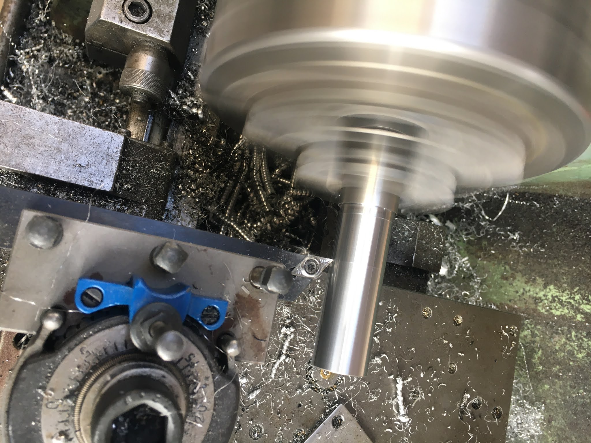
Make a stub to hold the plastic (nylon?) fan:
Cut those vanes back a bit. Can't imagine it's going to compromise the thermal behaviour much - not on a Bantam at any rate.

And trim the register back a bit on the other size, to reduce the gap between the fan and the motor housing:

Now cut the cowling back, otherwise all that fan trimming will be in vain (vane?). I think this is the very first time I have ever used this Mitutoyo height gauge, to scribe a line at the desired height. They look nice but like a shaper machine they seem to have very little application in my workshop.

There. I need to hack the shaft back a bit, otherwise it's looking reasonable

A new, larger bore Taperlock insert arrived from Bearingboys (£6), as the shaft is 28mm instead of 19mm. I can mount the pulley right up against the motor, although the shaft sticking out doesn't appear to foul anything, so I shouldn't need to cut it back.

Now for some manual work. This is why machine tools were invented but there's no point messing about with the bandsaw here.

Sorted.

Finished. Used some bearing retainer to hold the fan to the shaft.

Ready for action. That seems to measure up against the space available.

Now to modify the mounting plate for the larger motor. Or more accurately, to replace the plate, as the motor foot mounting holes coincide with the existing slots in the original plate. Luckily I seem to have some 3/8" loominum plate that is almost exactly the right size.


