Saturday 16 June 2018

It moves - ATC alive again!

Now that I've had a chance to see what I've got here, strip it down, figure out how it works and what the components look like, it's time to slap it all back together again and see it in action - on the bench of course.

Reassembly:

The boards go back again quite easily and the connector pairings are fairly obvious. Although there are several instances of the same connector type, they are mostly only partially populated so even a blind idiot can work out the correct connectors to mate. It's possible that a fat and stupid idiot might make a mistake but that's another matter.

I have a 110V isolation transformer already set up in the garage to power some of the Mercan tools I brought back from Canada and I have a bench PSU that should suffice for the 24VDC supply. So I wired up some cables for each and connected them up.

First I cleaned up the cable glands. Wasn't strictly necessary but I couldn't help myself and it only took 5 mins. A bit of Gunk and some hot water did the trick:


Box back together, front panel back in place and connected to the terminal block:


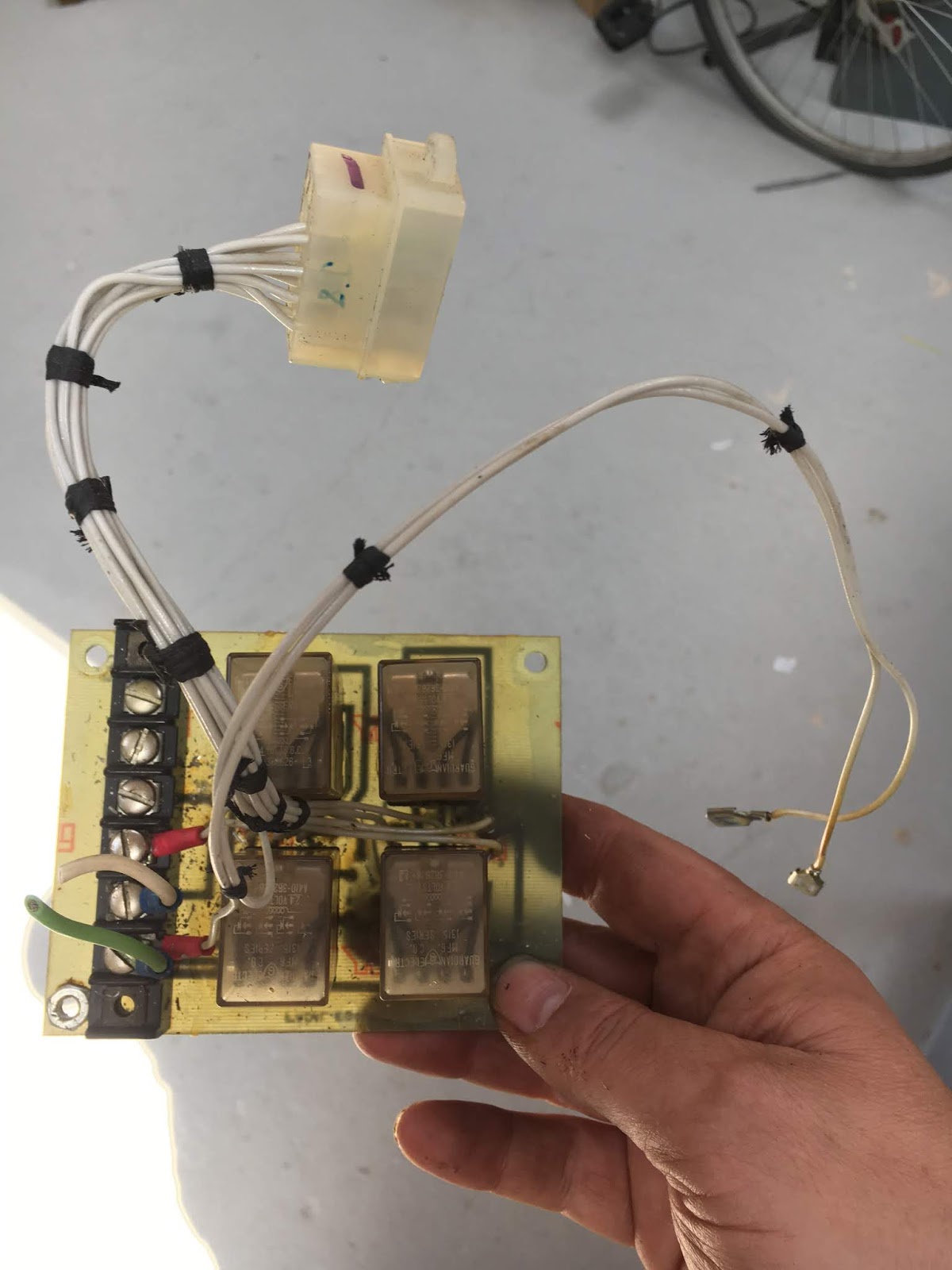
Back on the main assembly and wired up, ready for action:


Compressed air:

Now I need to get some compressed air to it. As ever, pipework is a bloody fiddle - everything has to be the right thread, diameter, fitting type etc etc. Naturally I didn't have anything suitable and even the ones I have are BSP, while I suspect the Mercan fittings are some local flavour. This is the sum total of my compressed air fittings. And I have a combined regulator / oiler that has some potentially useful adaptors on it. 


Tried a few things but ultimately I needed some 8mm plastic pipe, which I simply don't have. Had to make an adaptor piece from steel and hold the connection in place with cable ties. I drilled this out and soldered it into a std PCL quick fit connector. 


Obviously the gripper teeth don't grip onto steel quite as well as they do with plastic, so cable ties were required. This is the manifold block - the air inlet is on the back left face.


It'll do for now but I will need to buy something more permanent:


Ready to go!


The arm swings in and out. The claw works using the manual control on the front panel but doesn't seem to do anything when the arm is doing its business. I don't know if this is normal. If so, the controller will have to take care of the claw in addition to moving the carousel, arm etc.

So here we are. I'm holding the claw closed manually so that it doesn't drop the toolholder. Otherwise it seems to be behaving:


The thing seems to have survived being taken apart and put back together again.

Geneva Mechanism:

It just hums when I press the switch. No movement, so something's not right. Ah, the fat stupid bloke had been busy in there when I wasn't looking and didn't connect up the motor running cap. I noticed that the motor had 4 wires and stupidly thought it was a universal motor. How dumb - an induction motor is much better suited to operating at a reasonably constant speed.

Seemed a good excuse to take the Geneva mechanism apart and give it a clean up / run my pork pie over it.

Here's the motor - very simple, being an induction motor.


The baseplate cleans up nicely with the motor and carousel chain thing out of the way


Wheel back on. It has an eccentric for tensioning the chain.


There's a needle bearing under the motor end.


After cleaning up, the Geneva mechanism seems to be in pretty reasonable condition.


Microswitch back in, mechanism greased up:


All back together again. Works nicely.

Sunday 10 June 2018

Stripping down, cleaning up and investigating the ATC

Taking a closer look:

Now that it's in the workshop, it's time to get it onto the bench and take a closer look. First, clamp it to a trolley so it doesn't fall off - it's a bit top heavy:


There's a convenient feature for lifting: 


Up onto the bench:


Take a closer look. These are the solenoids:


This cable wasn't connected to anything. It used to go to that air pressure microswitch at the left:


Each of the main subassemblies has its own connector. So the main board can be disconnected fairly easily.


Electrical stuff:

Here it is. The wires solder to the bottom of the board and all the connectors are inline. The harnesses are old school, with waxed lacing. Haven't seen that for a few years.....


Here's the main (ie relay and diode) board with the 12V regulator and 555 timer at the top:


Underside. It's been laid out by hand with Letraset tape and Dalo pens. The idents are hand written in the copper. It will take a bit of deciphering....


So, may as well take a few pics for the record....


This funny board has a classical C230B thyristor (25A 200V) and a couple of pots and resistors. I assume it's a timer for the power drawbar. All handmade, with no actual copper tracks.


The Geneva mechanism has just the motor and what looks like a position switch:


The front box has loads of switches and includes the optional up/down speed controller. Not relevant to my machine which has a fixed pulley and factory VFD.


Here's the underside of the spindle speed "up down" controller:


Cleans up nicely with WD40, tissue and elbow grease:


Similarly the rest of the gubbins:


With the front switch box removed, it all cleaned up nicely. 


How does it work?

Having cleaned it up a bit, next I need to figure out what the bits do. I assume the multicore cable is a 24VDC input jobby that directly drives the relevant relays. There seemed to be a pair of (24VDC and 110VAC) supply cables, so perhaps I can start by tracing them and the multicore cable back...

Yes, sure enough, the 24VDC come in on the terminal block at the front, goes through a fuse, then the manual / auto switch and then onto the main board. There's an LED for each mode. And the 110VAC also comes in on the same terminal block, through a fuse and the same manual / auto switch (different contacts obviously) and over to the main board. 

The LM340K-12 regulator (in a TO-3 can) is massive overkill. It simply powers the 555 timer, which drives a 2N3904 (NPN) signal transistor (through a 6k8 resistor) which in turn drives a 24V relay. It's clearly just a delay timer to allow the power drawbar (PDB) to engage before the motor spins. I won't be using it anyway.

So the board has a mixture of 110VAC and 24VDC (and a little bit of 12VDC). I'm pretty sure the 110VAC needs to be isolated, as it seems to be grounded and even if it isn't, the creepages and clearances for US equipment back in the 
70s probably lacks a little of the safety margins we'd expect today.

It also looks as if the Geneva mechanism motor is 110VAC, as suspected, although this should become clear when I power it up. 

The forest of diodes are all the same type - 2A / 200V glass passivated avalanche diodes 1N5059. Never heard of them but they seem to do the job of flywheel diode (for the relays) and ORing diodes for the "logic".

Don't see any obvious reason not to power it up, although I should try to figure out the various inputs on the multicore signal cable first, as it will be tricky once the main board is back in place. It should all work in manual mode of course but the final outcome would be something that works in auto mode is using remote inputs via that signal cable. 

How to control it?

I have a couple of Arduino Mega 2560s which would be capable of handling loads of IO but if I were to gut the whole thing and completely replace the logic with an Arduino, it would require a massive amount of reverse engineering. If I can get the thing to behave in "auto" mode, I may be able to write something in "PLC" code for the Centroid Acorn to do the control logic.

I could just about make do with providing inputs like "index forward", "index reverse", "tool in", "tool out" etc and outputs such as "indexing finished", "tool home position" etc. Having said that, I think I may struggle to find enough free IO on the Acorn.....

Did some wire tracing and comparison with the schematics which confirms that said schematics are quite different - names, colours, pin numbers - they describe a significantly different product. However, the basic functions are unlikely to have changed. Here are a few notes for (my) records. 


And FWIW, here's a barely legible label that I suspect identifies the connections to the VFD UP / DOWN board:


I can just about make out words like "RPM", "TURRET", "DIRECTION"

    1. RPM   GREEN
    2. RPM   WHITE
    3. RPM   BLACK
    4. __ET  RED
    5. __ET  BLACK
    6. REVERSE   BLACK(???)
    7. ___   GREEN
    8. CHANGE   MOT(???)
              ...DIRECTION

Typewritten paper labels and 40 years of oil haven't helped to make it legible...

Next steps:

I'll reassemble the main board into the machine and prepare to power it up. That will have to wait until next weekend when I return from working away during the week.

I need to get into programming Centroid Acorn "PLC" code. God knows why they called it that, as it's neither a PLC nor any similar form of language from what I know. From my previous experiences with the Acorn, this is likely to be a not insignificant challenge, not least due to the patchy documentation.....

Final assembly and test of the spindle nose adaptor - RESULT!!

After the recent distraction caused by the 3D scanner, resurrecting the 3D printer and buggering about with the throttle bodies for my Honda...