Thought you'd given up on this?
Bloody finally, after endless distractions and diversions, I've managed to get enough time in the workshop recently to finish wiring up the cabinet for the Bantam. I had the system working on the bench as a lashup, to prove to myself it was a runner. This last stage has been putting together the "proper" system in a pukka cabinet, with my half arsed version of industrial wiring.
As on my previous attempts, I've fitted the isolation switches, circuit breakers and (in this case) DIN rail PSUs on the rear of the front panel (aka door), keeping most of the mains wiring off the main chassis plate. In fact, given the relative simplicity of this 2 axis lathe system (including mains powered servo drives), there's not a whole lot of shit in there, so the main chassis plate merely holds the drives, VFD and the PC. I've mounted the Mesa boards on the top surface of the PC, pre-wired as much as possible onto Dsub connectors for the encoders, with the 5i25 >> 7i76 + 7i85 ribbon cables kept nice and compact.
So this was mainly a question of mounting all the myriad IO connectors (PC peripherals, VFD remote operator panel, PC power / reset switches, cooling fan, e-stop switch etc etc, then "just" wiring the damned things up.
Metal bashing:
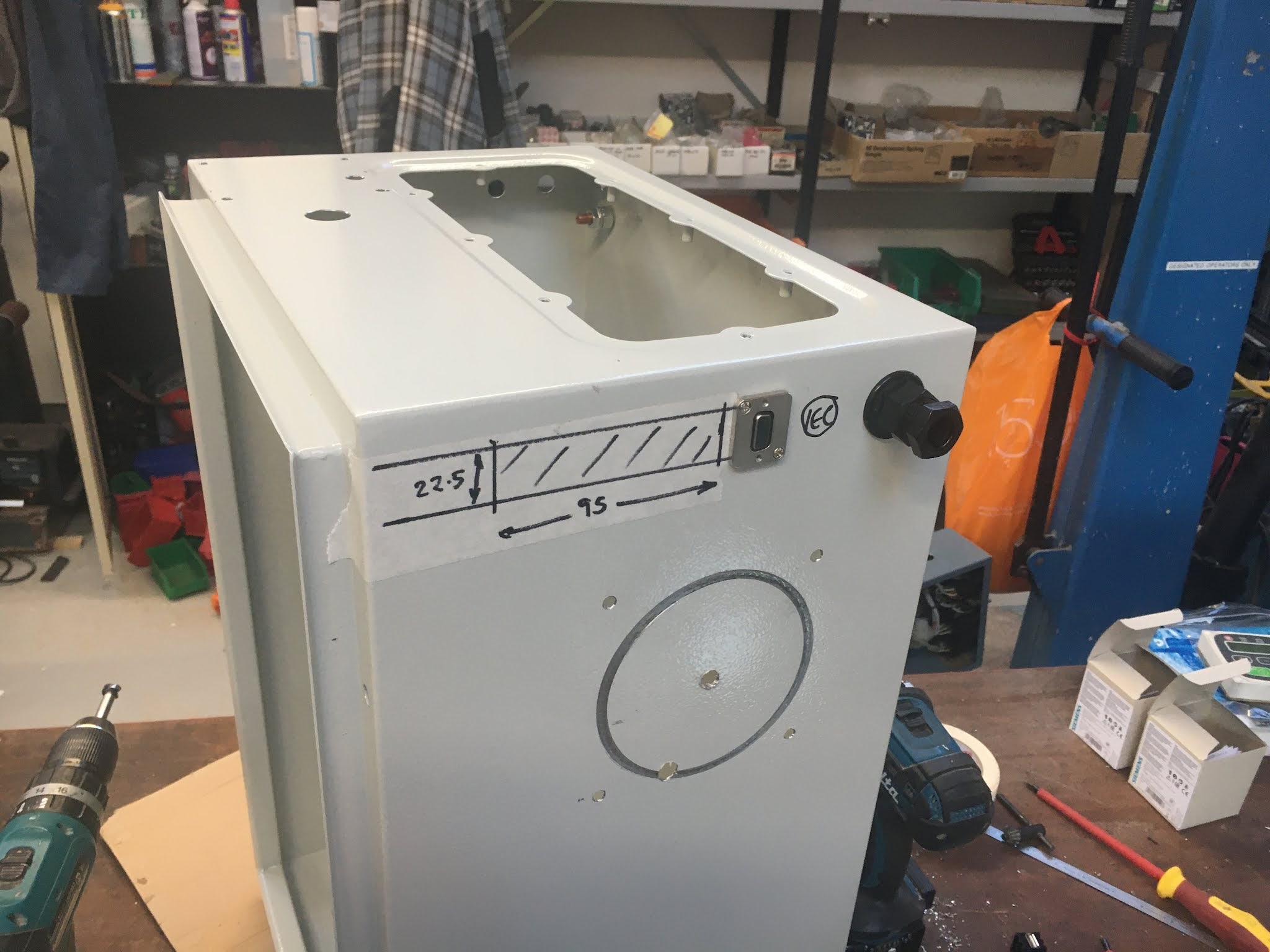
Some of the holes simply require a circular hole, such as the cable glands and the VGA connector. The 120mm fan openings didn't happen when I tried to use the hole cutting saw - although I have several new, decent quality hole saws and they are designed for metal cutting, I gave up trying when it became clear this wasn't going work out so well.
Ended up using the jigsaw once I'd got some fine pitch (1mm / 25tpi) blades for it. Apart from anything else, this allowed me to cut the rectangular openings:
Wiring up the main cabinet:
VFD remote operator panel wired in:
And the various PC sockets (HDMI, VGA, USB, ethernet etc) wired in to the PC:
This fan grille isn't a particularly good fit, as it doesn't seem to be designed to sit flush on a flat surface. Not sure what the stupid idea was there but it will do for now, until I buy something better.
Power and reset switches for the PC - I need some way to power it up and do a reset if it misbehaves:
Front panel:
This is the basic layout for the front panel:
Getting there now. So time for a long mains lead and plug.
Front panel wired up and ready to be tested:
Slightly unconventional concept here, integrating the Mesa cards with the PC but it makes for a compact implementation:
Does it work, fatty?
Time to start powering it up! Step by step - check the PSUs are connected to the right points in the correct polarity etc.....
Well that seems to have gone well. First step was to power up the PC then connect the Mesa cards back in - and it works. Here's the proof:
I now have 2 monitors - one for the main Probe Basic display (which likes to hog a display on full screen mode) and the other for running a browser, Visual Studio Code etc.
Is that it then?
Obviously at this stage I haven't connected the servos, spindle motor, limit switches or encoders but they should be a big step, as the Mesa cards are up and running. Give or take a couple of crossed over signal wires, I don't see anything significant likely to crop up.
So what's next then?
Although that seems to be a major milestone, at the moment I have little more than a rather odd looking PC in a large steel cabinet. I'm going to have to move things on a bit now:
- Connect the limit switches to ensure safe containment of the movements.
- Connect up the encoder scales - the axes won't be able to operate without them, as I am running closed loop.
- Connect up the servos and check they still run.
- Connect up the VFD.
- See if the spindle encoder is still working correctly.
That should keep me quiet for a while.