Sunday 25 September 2022

Refitting the enclosure - Boys Own epic!

Getting the enclosure back on the machine is going to take some buggerage. I could wait for one of our boys to wake up and give me a hand but as they are both currently nocturnal, I could be in for a long wait. A better idea might be to play Tetris with the engine crane, then use it to manoevre the enclosure into place. The issue with that is the long legs, which will want to fight with the frame of the lathe.

First, I'll need to move the TIG welder out of the way. I forget how much it weighs but you wouldn't want to drop it on your toes..


That's better. Let the dog see the rabbit etc.


With some straps, I can start to move it into position.


The crane just lifts it high enough to clear the machine.


Getting there...


Boom. Got there finally. Nothing broken.


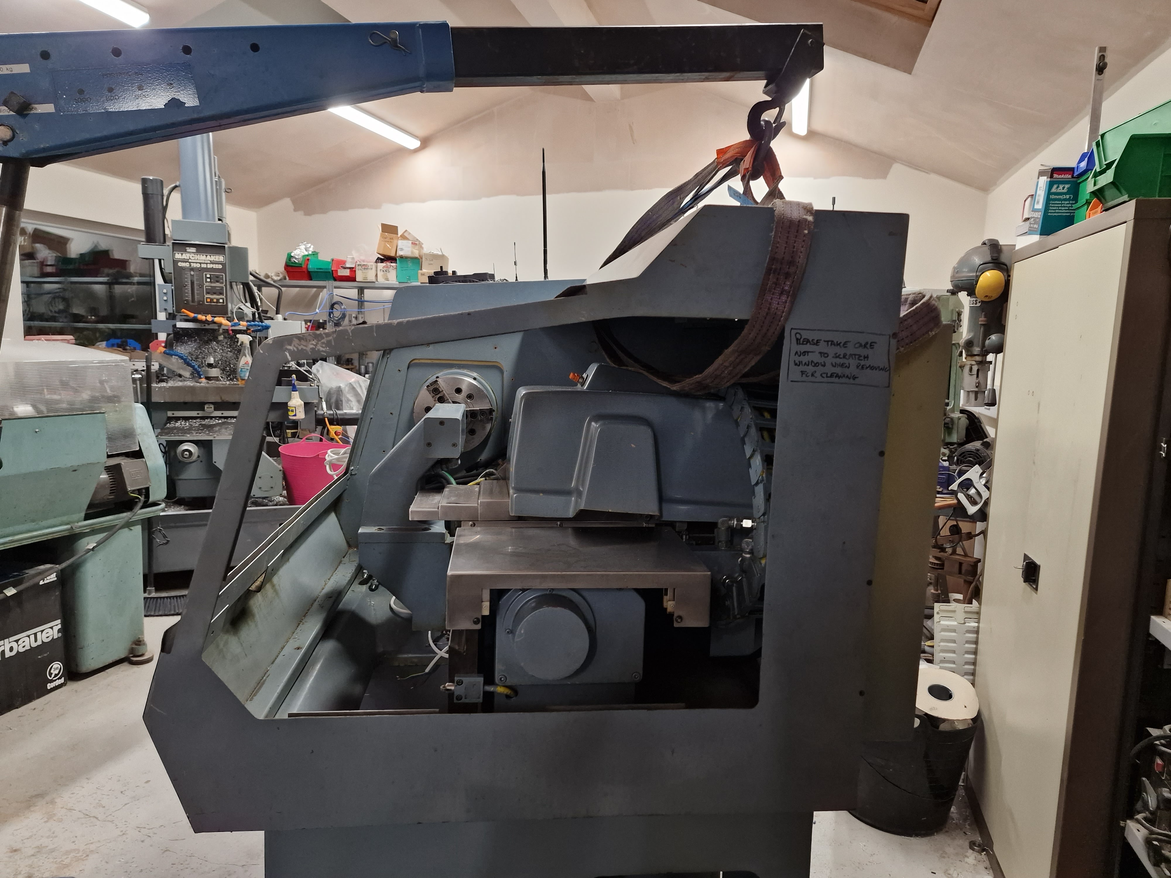
Need to extract the straps, otherwise it's looking good.


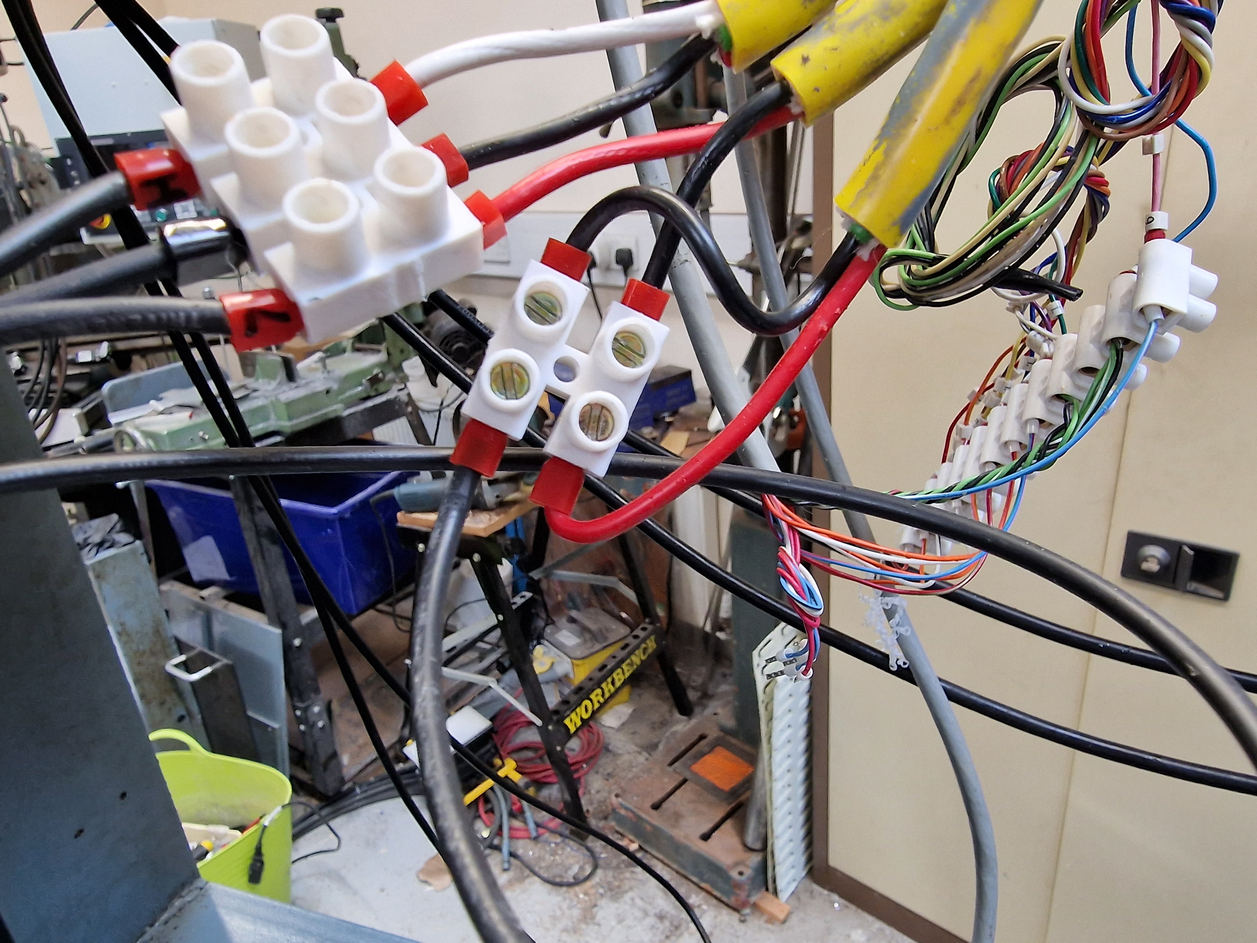
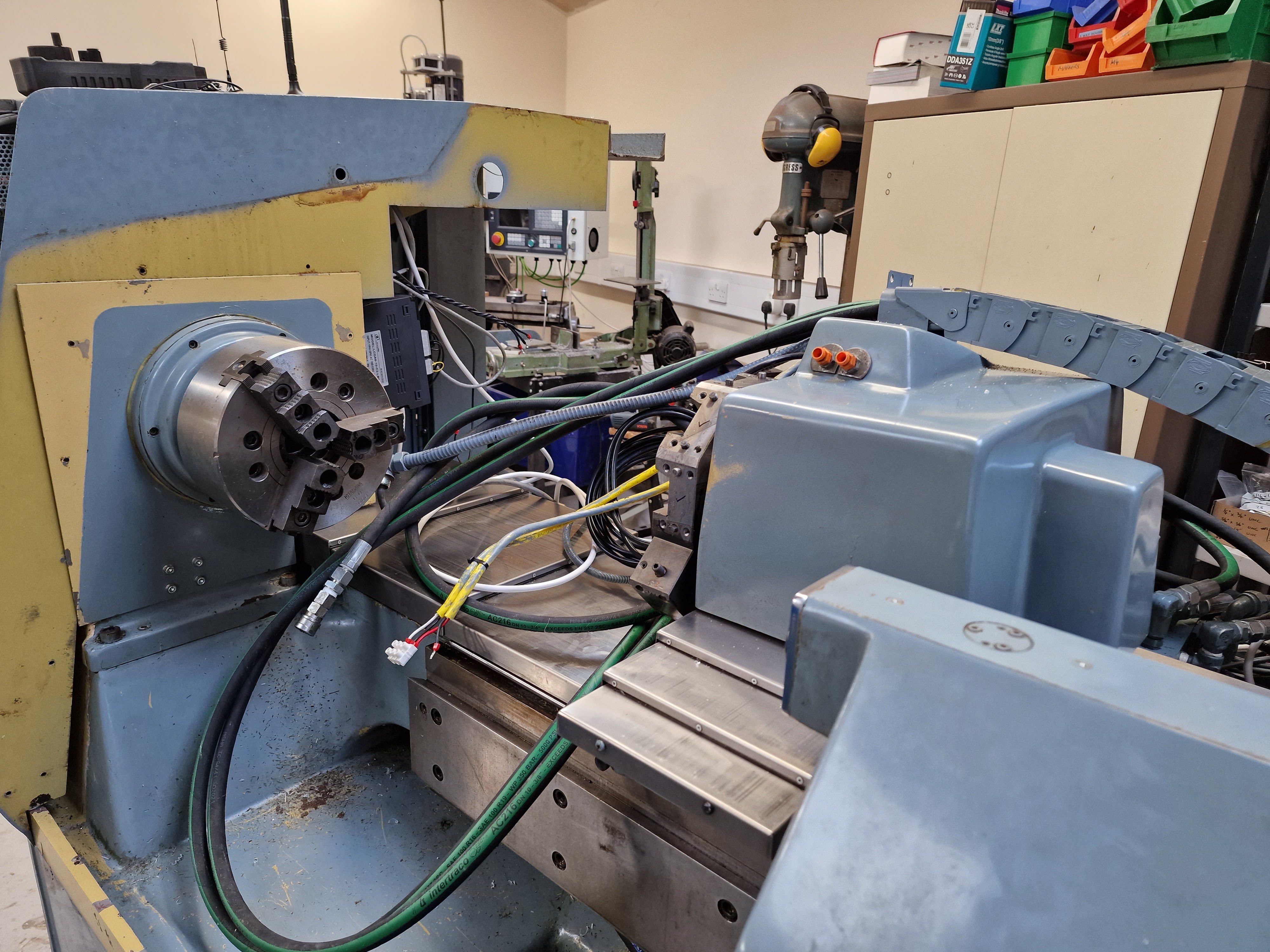
Now I need to feed all the hoses and cables through the hole in the enclosure. Those hoses are pretty rigid and won't be twisted, so I need to move the carriage towards the headstock so I can gain some movement. The ballscrew has a short 1/4" nose where the encoder used to attach. This is a handy feature that allows me to use the cordless drill driver to turn the ballscrew once the cover is removed.


Wahay. Sorted.


Now I *just* need to connect them up again. I can safely say I won't be taking that off again in a hurry.

Saturday 24 September 2022

Preparing to refit the enclosure

Right. Let's get this machine ready to refit the enclosure. It's working convincingly enough to make me feel I can risk it. So I'll need to disconnect all the cables and hoses that come up the drag chain from the carriage. They have to be threaded through a hole in the enclosure, so there's no way round it.


I need to fit the blanking plate at the tailstock end first, as it won't be possible with the enclosure in place:


And there's a lot of cleaning to be done. Like all the years of glop on the turret housing. WD40 and a white scouring pad should do the trick.


That's better.


On it goes.


It's held in place by the 2 snap lock hose couplings.


Next, remove all remnants of the crappy mastic stuff under the enclosure.


Carefully note (photograph) the limit switch connections:


And the turret position switch connections.


And the turret solenoid line:


Then remove the hoses for the turret hydraulic flow and return:


There. All disconnected and sort of out of the way:


Let's get this thing lined up and ready to go back on.


Ready for the enclosure....

Tuesday 20 September 2022

ISO lathe toolholders and inserts

I've got a bit of an idea of how the ISO numbering system works for milling cutters but my understanding of turning tool numbering is sketchy to say the least. Might be a good time to brush up, as I am planning to buy some tooling for the Tree.

Numbering system:
Have a look at the Korloy cutting tools catalogue for a definitive reference. In the meantime, here's the toolholder system at a high level:


Thus, "DWLNL2020K08" is:
  • D: clamp type ("top and hole clamp")
  • W: insert shape (trigon - which has 80 degree tip angle)
  • L: insert angle (95/95 degrees ie +/-5 degree clearance for trigon inserts)
  • N: clearance angle (zero degrees - double sided insert!)
  • L: LH or RH (left handed shank here)
  • 20: shank height (20mm)
  • 20: shank width (20mm)
  • K: shank length (125mm from insert tip to rear of shank)
  • 08: length of cutting edge (8mm)
NB: some turning inserts ("V" shape for instance) have long "cutting edges" relative to their size - this is a key difference between the numbering system for milling and turning inserts. Milling inserts seem to default to the "inscribed circle", which makes less sense for some turning inserts, given the wider variety of turning insert shapes.

NB: The Tree seems to be intended for 125mm length toolholders ("K" length according to the ISO convention). I may as well specify all toolholders to this length so that the tool length offset is pretty close and consistent for external tools.

The "N" (negative) inserts have zero clearance angle on the insert. The clearance is provided by the angle at which the insert is presented to the work. The upside of these inserts is that they are double sided, so a trigon insert thus has 6 edges (or corners depending how you look at it). They also require a more positive clamping solution than a screw to prevent the insert sliding off the toolholder into the workpiece.

Clamping types:
To date, most of my lathe tooling has used the screw ("S") system, using "positive" inserts where the front clearance angle in provided by the insert itself. Keeps things pretty simple but the alternative clamping methods look more secure and also come with the advantage that the negative inserts used are typically double sided. The tooling that came with the machine are the "clamp and pin" variety, while the Teknik branded trigon toolholder I bought from Cutwel recently had a "lever lock" clamp. I prefer the look of the "clamp and pin" flavour, not overlooking the availability of the various toolholders and inserts on the likes of AliExpress.


Turning Inserts:
For completeness, I need to be able to define / identify suitable inserts for any toolholders I have or obtain. Here's the ISO insert numbering system from the same catalogue. It's very similar to the milling insert system but clearly there are different insert shapes so it might be a mistake to assume they are the same:


As an example, a suitable insert for the toolholder example above might be "VNMG160404-MP":
  • V: 35 degree diamond shape (definitely not a milling insert)
  • N: zero front clearance ("negative" insert, where the clearance is provided by the toolholder)
  • M: tolerance
  • G: cross section type (suitable for a locating pin rather than a screw)
  • 16: cutting edge length (16mm here)
  • 04: height code for cutting edge (actually 4.76mm)
  • 04: nose radius (0.4mm)
  • VB: chip breaker shape (this will often be specific to the manufacturer I suspect)

"Handedness"(?) of the toolholders:
As noted previously, it's clear from the construction of the ATC turret that the Tree spindle needs to rotate "backwards" relative to a conventional manual lathe (ie clockwise) and present the toolholder with the insert facing up. Or in simple terms, external tooling needs to be "left handed". 

On the other hand, internal tooling should be presented upside down (boring bars) and the spindle needs to rotate conventionally (ie counterclockwise) for boring bars and drills. That's handy, as I'm not aware of having seen "left handed" boring bars. The only place I could imagine them being needed would be on a secondary spindle which sounds expensive.

Final assembly and test of the spindle nose adaptor - RESULT!!

After the recent distraction caused by the 3D scanner, resurrecting the 3D printer and buggering about with the throttle bodies for my Honda...