Sunday 28 February 2021

HTD3 timing pulley machining

Choices:

Given that the supply of general purpose HTD pulleys seem to come almost exclusively from random Chinese factories, I could either order a shit load of randomly sourced pulleys and hope they contain an example that comes close to meeting the approved tooth profile.

The alternative seems to be to have a go at machining one of these boys myself. Being a bit of a gadfly, this naturally appeals to me. Why buy something when you can spend several days buggering about with it yourself?

How to machine your own HTD3 timing pulley? 

Obviously I could use a ball end mill but the surface speed at the centre of the cutter is zero and the chances of milling 32 slots of 40mm or so without breakage and with a half decent surface finish seem slim. Then there's also the challenge of finding a suitable 1.8mm diameter ball end mill. 

From APT-Tools, I also have a couple of long necked 1.8mm ball end mills. These look admirably fragile but are a fallback ie hopefully they will be a drawer filler (previously the smallest ball end mill I had was 3mm), rather than a primary route.

If I were to mount a boring bar as a single tooth indexable cutter, I could machine the slot from the side (rather than from above), if I could figure out how to select and set up the right toolpath.

I have one of these Korloy mini boring bars. No, I didn't pay £60 - presumably it was on offer at the time, which is when I tend to buy stuff like this from Cutwel...


They would be almost bang on the required radius size (1.82mm technically, from what I can find). 

Furthermore, I also have a couple of tiny corner radius end mills with 0.5mm radius. That will allow me to corner off the sharp corners of the resulting slots. Technically, they should be 0.3mm radius but I reckon 0.5mm would be close enough for this application, assuming I have the basic slots made to dimension.

I seem to recall John Saunders posting a Pootube video on this. Sure enough, here it is:

That seems simple enough. I should have this toolpathed up in no time! Wrong...

Creating the toolpaths:

Things got interesting about here. No point in repeating myself, so better to link to the post I made on the Fusion manufacturing forum.

Finally, I have a working toolpath for the slot and one for the chamfer operation, each repeated in a circular pattern (32 times) to form the complete pulley.


%
O05000
(5000)
(32t pulley)
(T2  D=9.4 CR=0.91 - slot mill - 1.8mm round side cutter)
N10 G90 G94 G17
N15 G21
(5555 main slots 2D Contour3)
N20 G28 G91 Z0.
N25 G90
N30 T2 M6
N35 S6000 M3
N40 G54
N45 G0 A0.
N55 G0 X9. Y-18.285
N60 G43 Z2.247 H2
N65 G1 Z-0.924 F333.33
N70 X4. F120.
N75 X-39.
N80 Y-23.285
N85 G0 Z2.247
(5555 main slots 2D Contour3)
N95 G28 G91 Z0.
...
etc (another 31 tiumes)
...

N1960 G28 G91 Z0.
N1965 G90
N1970 A0.
N1975 M30


Off we go:

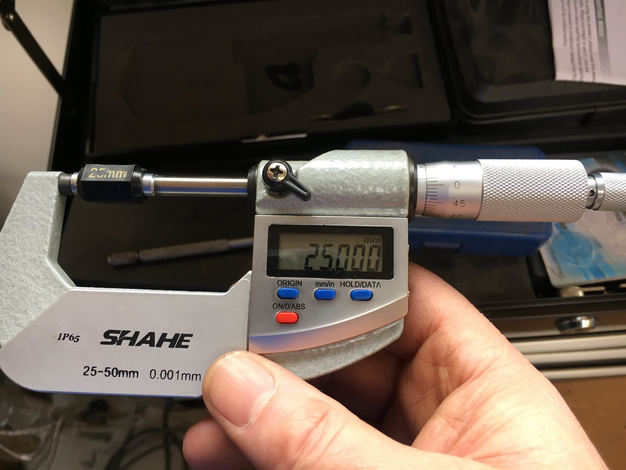
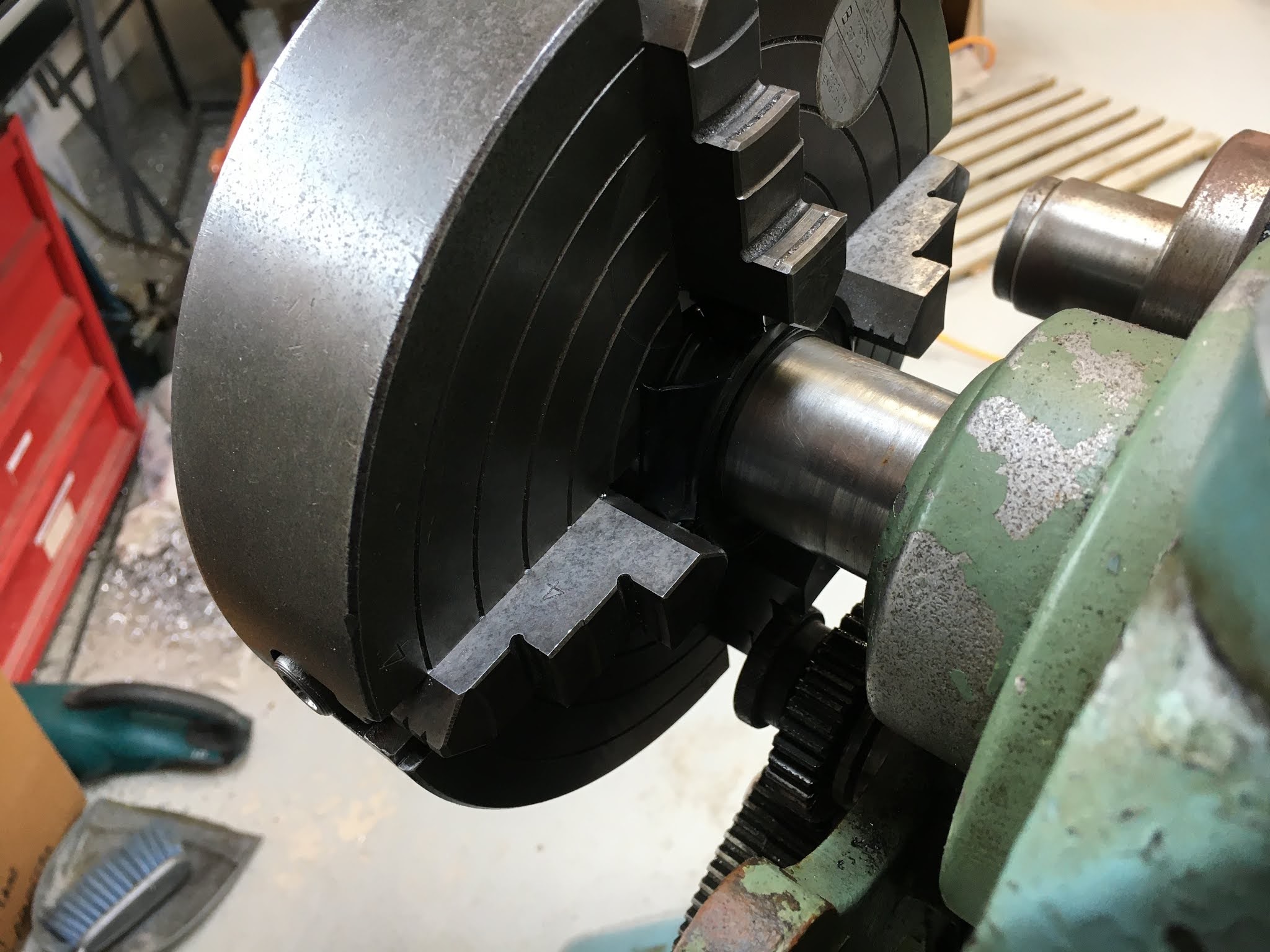
But first, let's turn down some bar stock to the right diameter. I have some 1-1/4" mystery loominum I think I picked up at a steam fair (Old Warden?), so that needs to come down from 31.75mm to 29.8mm or so. Without graduated scales on the lathe, I have to hit the diameter by trial and error, ideally within 0.1mm or so. 

This came out well. I wanted to leave the whole length intact, as if I cut off a 5-6" length each time I want to run a trial, I will get through it in no time. The thru bore on the 4th axis can handle 30mm (even if the lathe can't), so it seems the right thing to do.
Into the 4th axis, ready for action. I finessed the tool diameter to 9.4mm, having determined by trial and error(!) that the original calculated tool diameter of 8.5mm was a bit on the small side. This shows up when the tool cuts too deep and, ahem, the shouder of the insert joins in the action. 

Show me:

First groove cut at v slow feedrate. Looking good!


So let it continue to the end:


Although the chamfer isn't there yet, the belt fits at least. 


That's a good start. However, if I don't radius the edges, the belt will probably get eaten in no time.

Let's see how the corner radius operation comes along...


We'll call that a success.

Wednesday 24 February 2021

How to add 7i85 board to 5i25/7i76 combo

Although I'm not quite ready to integrate my X and Z linear encoders with my LinuxCNC system, I have the 7i85 board already. I 'll need that to support the extra encoders above the single instance that the 7i76 supports. generally that's going to be used for the spindle encoder that you'll want if you want to measure actual spindle speed and the all-important rigid tapping.

Here's an overview of some of the Mesa cards.

The 7i85 is a "dumb" card ie it has no FPGA onboard, so doesn't require reflashing to set up the various IO. Instead, the 5i25 within the PC needs to be told to expect a 7i85 to appear on the end of the 25 way parallel cable.

The default firmware provided in the 5i25 when they ship it is configured for 1 or 2 of the 7i76 daughterboards. So I need to change the firmware within the 5i25. There's a bitfile for a 7i76 / 7i85 pairing, so the process is like this:

  • Download the 5i25 zip file from Mesa Electronics containing all the available bitfiles.
  • Use the mesaflash utility to flash the 5i25_7i76_7i85.bit bitfile into the 5i25.
  • Reboot the PC to power cycle the 5i25 so the changes take effect (yes I forgot).
The 7i76 should continue to operate as before (no need to reconfigure it). The 7i85 (being a dumb board) should simply appear as additional IO on the 5i25 board. In this case I should be able to set up as many as 4(?) encoder inputs and something like 5 RS485 interfaces.

Luckily, mesaflash is included in the std LinuxCNC install, so as long as you avoid capitalising the first letter and remember to issue the sudo command first, it will go like this:

muzzer@LinuxCNC:/lib/firmware/hm2/5i25/configs/hostmot2$ sudo mesaflash --device 5i25 --write 5i25_7i76_7i85.bit
Checking file... OK
File type: BIT file
Boot sector OK
EEPROM sectors to write: 6, max sectors in area: 16
Erasing EEPROM sectors starting from 0x100000...
|EEEEEE
Programming EEPROM sectors starting from 0x100000...
|WWWWWWWWWWWWWWWWWWWWWWWWWWWWWWWWWWWWWWWWWW
Board configuration updated successfully.
Checking file... OK
File type: BIT file
Boot sector OK
Verifying EEPROM sectors starting from 0x100000...
|VVVVVVVVVVVVVVVVVVVVVVVVVVVVVVVVVVVVVVVVVV
Board configuration verified successfully.

You must power cycle the hardware or use the --reload command to load a new firmware.

That worked and the 7i76 config remained intact - TFFT!

HTD3 timing belts and pulleys - how can they be this crap?

What now, fatty?
Bastard nightmare. Having finally assembled my precision ground ballscrew, back-to-back thrust bearings and servo motor, there is a shit load of backlash between the motor and the ballscrew, equivalent to around 100um of linear motion. Even a blind man could see this in the dark.


WTF?? Is it the belt or the pulleys? Almost certainly the pulleys you'd think, as the belt surely isn't going to be shipped like that. On the other hand, the pulley stock used in the production of these (mainly hobby) pulleys is probably flung out by the skip load in some shithole in China with little regard for quality.

So what should it look like then?
Let's find out what we should be seeing when we look at an HTD3 pulley:

and 

Sure enough, when you look for the "approved" dimensions for the HTD3 tooth profile, you find:

To summarise - approx 1.9mm across the throat and 1.1mm across the top of the teeth. 
And what do we find?


Let's call that 0.6 - 0.7mm across the teeth. So I'm seeing around 0.5mm backlash on each pulley, equivalent to ~1mm total backlash. You can hear the wind howling through the gap between the belt and the pulley. Jesus shit and piss.

With a circumference of around 72mm for the 24t pulley, 1mm of backlash is equivalent to ~70um. That's in the sort of ballpark I'm expecting - ballpark being the operative word here.

So that makes a mockery of my ground ballscrews and 2500 steps per rev servo motor. 

The choice seems to be to randomly buy a load of HTD3 pulleys from a wide range of suppliers and hope some are actually better than this - or perhaps try my hand at making my own. Never one to avoid an unnecessary complication, I may be tempted to go for the latter. Dumb fuck or what? Watch this space...

Incremental changes to .ini and .hal files using the PNCConf tool

Background:
Now that I've got the Probe Basic Lathe (PBL) GUI set up and working, I need a simple method for making changes to the .ini and .hal files as I configure and evolve the setup.

As the current working files had to be manually fettled (quite extensively) after initial creation by the LinuxCNC config tool, I can't simply go back in with the PNCConf tool to make changes. If I do so, most of the painfully created edits will be overwritten and I will get quite upset.

My Cunning Plan is to create 2 almost identical system configs using the PNCConf tool, with the second instance differing only by the incremental change I am hoping to carry in to my PBL configuration. Then I can use Visual Studio Code (VSC) to compare the contents and highlight the differences. I can then manually update my PBL system by copying and pasting in the relevant content. I would do this for each change I need to implement. Sounds simple enough?

Current Status:
I have the PBL setup working on the bench. It spins the servos and appears to home correctly when I trigger the home / limit inputs manually using 3 microswitches lying on the bench. However, there was some modest progress last night when I wired up actual the X Axis microswitches on the machine itself. I'd like to get those wired up and working correctly before powering up the servos on the machine. This is what it looks like with the cross slide removed:


Here's what I've got right now in the HAL file on the homing / limit switch front. It works nicely if I manually trigger the microswitches at the correct moments:

# --- BOTH-X ---
net both-x     <=  hm2_5i25.0.7i76.0.0.input-00-not
# --- BOTH-Z ---
net both-z     <=  hm2_5i25.0.7i76.0.0.input-01-not
# --- ALL-HOME ---
net all-home     <=  hm2_5i25.0.7i76.0.0.input-02
....

#*******************
#  AXIS X JOINT 0
#*******************

# ---setup home / limit switch signals---

net all-home     =>  joint.0.home-sw-in
net both-x     =>  joint.0.neg-lim-sw-in
net both-x     =>  joint.0.pos-lim-sw-in

#*******************
#  AXIS Z JOINT 1
#*******************

# ---setup home / limit switch signals---

net all-home     =>  joint.1.home-sw-in
net both-z     =>  joint.1.neg-lim-sw-in
net both-z     =>  joint.1.pos-lim-sw-in

It's quite easy to see how the input-00, input-01 etc inputs into the 7i76 are connected by the coloured nets to the home-sw-inneg-lim-sw-in signals. The PNCConf tool generates these entries automatically, depending on the selections made in the various setup choices.

You can see from the photo above that I have 2 switches on the X Axis, namely a combined "Home + X Pos Limit" switch at one end and a "X Neg Limit" switch at the other. That's not how the above HAL entries are expecting to find things. I will need to use My Cunning Plan to figure out what those changes are.

First pass:
Let's create a simple, minimal setup using PNCConf. Choosing minimal options requires the following:
  • Define XZ / lathe configuration and a dummy name
  • Define stepgens for the X & Z axes
  • Accept default axis parameters
  • Select the appropriate switch inputs for the Home and Limit signals.
  • Then save and exit.
Here's what I have at the top of the "current" .INI file:

# external input signals 
 
# --- BOTH-X ---
net both-x <= hm2_5i25.0.7i76.0.0.input-00-not

# --- BOTH-Z ---
net both-z <= hm2_5i25.0.7i76.0.0.input-01
-not
 
# --- ALL-HOME ---
net all-home <= hm2_5i25.0.7i76.0.0.input-02
-not
 
#*******************
# AXIS X JOINT 0
#******************* 

# ---setup home / limit switch signals---

net all-home => joint.0.home-sw-in
net both-x => joint.0.neg-lim-sw-in
net both-x => joint.0.pos-lim-sw-in

#*******************
# AXIS Z
JOINT 1
#*******************

# ---setup home / limit switch signals---

net all-home => joint.1.home-sw-in
net both-z => joint.1.neg-lim-sw-in
net both-z => joint.1.pos-lim-sw-in


And the replacement:

# external input signals

# --- MAX-HOME-X ---
net max-home-x <= hm2_5i25.0.7i76.0.0.input-00
-not
# --- MIN-X ---
net min-x <= hm2_5i25.0.7i76.0.0.input-01
-not
# --- MAX-HOME-Z ---
net max-home-z <= hm2_5i25.0.7i76.0.0.input-02
-not 
# --- MIN-Z ---
net min-z <= hm2_5i25.0.7i76.0.0.input-03
-not
 
#*******************
# AXIS X JOINT 0
#*******************

# ---setup home / limit switch signals---
 
net max-home-x => joint.0.home-sw-in
net min-x => joint.0.neg-lim-sw-in
net max-home-x => joint.0.pos-lim-sw-in

#*******************
# AXIS Z JOINT 1
#*******************

# ---setup home / limit switch signals---

net max-home-z => joint.1.home-sw-in
net min-z => joint.1.neg-lim-sw-in
net max-home-z => joint.1.pos-lim-sw-in

Of course, there are also some minor changes to the .INI file too. If you don't catch those, stuff isn't going to work out well. There's only one here:

Before:
 
MIN_LIMIT = -0.01
MAX_LIMIT = 200.0
HOME_OFFSET = 0.000000
HOME_SEARCH_VEL = -1.000000
HOME_LATCH_VEL = -0.500000
HOME_FINAL_VEL = 0.000000
HOME_USE_INDEX = NO

HOME_SEQUENCE = 1

 
After:

MIN_LIMIT = -0.01
MAX_LIMIT = 200.0
HOME_OFFSET = 0.000000
HOME_SEARCH_VEL = -1.000000
HOME_LATCH_VEL = -0.500000
HOME_FINAL_VEL = 0.000000
HOME_USE_INDEX = NO
HOME_IGNORE_LIMITS = YES
HOME_SEQUENCE = 1


Presumably, if a limit signal is seen during homing, an error will be created unless you include that line. Easy thing to overlook!

So I will now test out the theory on the bench. Luckily, the headers on the 7i76 have removable plugs, so I can unplug the existing microswitches and plug in the machine's microswitch inputs instead. 

Sorted - works nicely. Rather a PITA to implement but I guess it will get easier with practice.

Mesa and halrun - how to check hal pins

https://forum.linuxcnc.org/27-driver-boards/30453-mesa-5i25-7i77-first-steps?start=30 

To check everything separate from LinuxCNC open a terminal and:

halrun
loadrt hostmot2
loadrt hm2_pci
show pin


That will load everything with default settings. You should see the 7i77 and 7i71 pins listed.

From the manual: "In normal operation CR9 must always be on. At power-up, CR32 should be off and CR33 on. At power-up, the red LED CR33 indicates a watchdog fault, which is expected before host communications are established. Once running, CR32 should blink at about 1 Hz for a 1 KHz update rate, and CR33 should be off. In setup mode CR32 and CR33 are both illuminated."

The commands above will always give a watchdog fault on all cards, as there isn't even a realtime thread running. If you want to check that the watchdogs go off then follow the above with

loadrt threads
addf hm2_5i25.0.read thread1
addf hm2_5i25.0.write thread1
start


Note that you can use tab-completion to enter commands at the halcmd prompt, which saves typing and makes it more difficult to type typos.

You can use setp and getp to set and read HAL pins (and, in fact do anything else legal in a HAL file) at this point. Then type "exit" to finish.

Sunday 14 February 2021

Spindle encoder bracket for the Bantam

What up?
I need an encoder for the Bantam spindle if I want to do threading later, which I certainly do. I have a spare one that came with The Shiz. Seems to work fine, despite scribblings on it suggesting it had failed. I'll need to keep an eye on it but after an inspection and cleanup, it looks good to go.
I bought a couple of 36t HTD 5mm pitch, 9mm width pulleys for this. I reckoned the diameter should be sufficient for me to bore one of them out enough to fit on the spindle tail, leaving just enough room for a grub screw to hold it in place.

Spindle pulley:
So let's bore it out. First, set it up, using 4 nuts to pack out the jaws - the steel belt guides prevent clamping directly, as they are pretty flimsy.


I need to open up the 8mm pilot hole to 1-5/8" (~41mm). 


This 25mm drill is the biggest I have.


Then it's a question of boring it out to size


Done


Let's check it carefully


That looks pretty close


After cleaning off some of the crap and rust from the spindle tail, it slides on - just.


Encoder pulley:
The encoder has a 1/4" (6.35mm) shaft but the pulley has an 8mm bore. Time to make up a bush.


There.


Spot on - it also provides the correct spacing of the pulley body from the encoder.


Assembly:
The encoder is a bit tricky to fit into the space available. It could either fit here....


...or here.


That's a convenient stud. I could replace the nut with a standoff. A plan comes together...


Mounting bracket:
But first, I need to make up a bracket for the encoder. This is some 1/4" loominum plate, chopped roughly to size in the bandsaw. I'll finish it later as it comes together.


Usual thing - drill....


....then bore out to size.


With a stepped bore, I can hold it in place with a couple of M5 screws. Then I can rotate the body to get the wiring to emerge where it's most convenient. 


It's tight in there but it looks almost workable. I can visualise a standoff in that gap to mount the bracket and allow belt tensioning adjustment...


Final assembly:
After some belt sander work on the bracket, we seem to be getting there.


That's pretty much it - just a bit of finessing with the belt sander and a carbide burr required. And yes, the cover DOES fit over the top of the gear train still. Just.


The cunning standoff concept worked out well. I have a female-female threaded standoff with 7/16" BSW (close enough to 7/16 UNC) at one end and M12 at the other. So it screws onto the banjo locking stud and allows the encoder bracket to be bolted to the other end as shown above. I can adjust the belt tension by swinging the bracket, although it hardly needs any as it turns out.

Finally, I will need to drill and tap both pulleys for a couple of M5 grub screws to finish the job off.

Grub screws and final assembly:

The placement of the grub screws is fairly critical, so best use The Shiz with the Renishaw touch probe to find the centre of the boss, then spot drill the hole position. 


Drilled through 4.2mm (M5 tapping) then counterbored 6mm before tapping M5. Sorted.


The spindle pulley has less meat (about 6mm), so needs a bit more thought. 8mm spot faced using a centre-cutting end mill, then spot drill and drill 4.2mm before tapping M5. Then a specially shortened grub screw (belt sander) to avoid contact with the belt. Nice.


So that's it all done and dusted. It goes together nicely, no contact / grinding bits. Cable tie to avoid the wiring getting digested by the gears.


Finally, refit the cover. Yes, it fits - just.


Job done!

Saturday 13 February 2021

LinuxCNC homing sequences - setting up homing in Probe Basic Lathe

Status:

I got homing sort of set up using the PNCConf utility and copied the changes into the Probe Basic setup - simply by copying the resulting .hal file across. That's he advanage of using the same name for the .hal file as the one autocreated by PNCConf for the Axis version.

I found I had to invert the switch polarity to get homing to work when I copied the .hal file from Axis to Probe Basic. I also had to add to add the parameter value for this line in the .hal file...

setp hm2_5i25.0.encoder.00.scale [SPINDLE_0]ENCODER_SCALE

...by going into the .ini file and inserting his line:

[SPINDLE_0]
P = 0.0
I = 0.0
D = 0.0
FF0 = 1.0
FF1 = 0.0
FF2 = 0.0
BIAS = 0.0
DEADBAND = 0.0
MAX_OUTPUT = 2000.0
ENCODER_SCALE = 4000.0
OUTPUT_SCALE = 2000
OUTPUT_MIN_LIMIT = 0
OUTPUT_MAX_LIMIT = 2000

I guess PNCConf must have inserted that into the Axis .ini file, although the vast majority of the changes are contained within the .hal file.

To avoid LinuxCNC bombing out at startup. So it appears that the .ini file had to have that minor change made in addition to the .hal file changes.

Homing:

Ho hum. But I have homing working wih Probe Basic now. However, there are 4 different schemes for the homing sequence and the various distances etc need to understood and set to suitable values. It's not difficult to understand in principle but you have to understand the naming and operating modes they have chosen to use before you can sensibly set values. So far I have been operating the microswitch whilst watching the GUI to figure out where to press and release it, mimicing the homing moves.

The homing sequences etc are defined here.


I don't plan to use the index pulse yet, so I should select one of the first 2 options.


So I need to set HOME_SEARCH_VEL and HOME_LATCH_VEL, as well as setting HOME_USE_INDEX to zero.

Each of the "Joints" has the following section:

HOME_OFFSET = 10.000000
HOME_SEARCH_VEL = -3.316667
HOME_LATCH_VEL = -0.500000
HOME_FINAL_VEL = 0.000000
HOME_USE_INDEX = NO
HOME_SEQUENCE = 1

How to set this stuff?

HOME_SEARCH_VEL:

This variable has units of machine-units per second. The default value is zero. A value of zero causes LinuxCNC to assume that there is no home switch; the search stage of homing is skipped.

If it is non-zero, then LinuxCNC assumes that there is a home switch. It begins by checking whether the home switch is already tripped. If tripped it backs off the switch at HOME_SEARCH_VEL. The direction of the back-off is opposite the sign of HOME_SEARCH_VEL. Then it searches for the home switch by moving in the direction specified by the sign of HOME_SEARCH_VEL, at a speed determined by its absolute value. When the home switch is detected, the joint will stop as fast as possible, but there will always be some overshoot. The amount of overshoot depends on the speed. If it is too high, the joint might overshoot enough to hit a limit switch or crash into the end of travel. On the other hand, if too low, homing can take a long time.

HOME_LATCH_VEL:

This variable has units of machine-units per second. Specifies the speed and direction that LinuxCNC uses when it makes its final accurate determination of the home switch (if present) and index pulse location (if present). It will usually be slower than the search velocity to maximize accuracy. If HOME_SEARCH_VEL and HOME_LATCH_VEL have the same sign, then the latch phase is done while moving in the same direction as the search phase. (In that case, LinuxCNC first backs off the switch, before moving towards it again at the latch velocity.) If HOME_SEARCH_VEL and HOME_LATCH_VEL have opposite signs, the latch phase is done while moving in the opposite direction from the search phase. That means LinuxCNC will latch the first pulse after it moves off the switch. If HOME_SEARCH_VEL is zero (meaning there is no home switch), and this parameter is nonzero, LinuxCNC goes ahead to the index pulse search. If HOME_SEARCH_VEL is non-zero and this parameter is zero, it is an error and the homing operation will fail. The default value is zero.

HOME_FINAL_VEL:

This variable has units of machine-units per second. It specifies the speed that LinuxCNC uses when it makes its move from HOME_OFFSET to the HOME position. If the HOME_FINAL_VEL is missing from the ini file, then the maximum joint speed is used to make this move. The value must be a positive number.


That seems to be the background. I'll need to figure out the distances and speeds when I have the X and Z axes finally running.....

Final assembly and test of the spindle nose adaptor - RESULT!!

After the recent distraction caused by the 3D scanner, resurrecting the 3D printer and buggering about with the throttle bodies for my Honda...