Retrofitting 1983 Shizuoka AN-SB CNC milling machine, Bridgeport mill, Colchester Bantam lathe and 1982 Tree UP-1000 CNC lathe with modern controls - and other workshop stuff
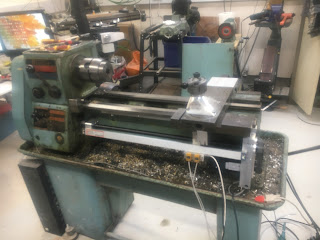
Time to report another serious accident with a mouse. This time resulting from a visit to a Facebook user group rather than a beer-fuelled ebay encounter. I haven't received it yet but here's what it looks like, sitting in the current owner's workshop:
It seems to have lost its settings, so doesn't actually work:
How bizarre - it's also a Matchmaker machine. They are the UK importer of these machines, as well as The Shiz itself. So I have 2 Matchmaker CNC machines that are matching in both badgework and paint colour. Also made within a year of each other (1982 and 1983).
Some (hopefully) superficial rust on the spindle nose cover and the ATC carousel.
Like The Shiz, it seems to be in reasonable condition.
There's a CRT monitor behind that smoked acrylic cover.
Another view of the headstock area.
Here's what a well restored example could look like, painted in brilliant white. Apparently this took many hours to achieve.
There was some guy selling a manual on ebay. Let's see what comes with the machine before splashing out on (possibly duplicate) documentation.
More examples, some more tragic looking than the others.
I played the violin both solo and in an orchestra from a fairly young age (8?) until I was around 15, by which time I'd got to about grade 7. Then stuff happened, like electronics, radios, motorbikes, cars, beer and women - and other shit besides. So the fiddling took a back seat. I still love classical music (and most other sorts) but it's now about 45 years since I tried to play the fiddle.
I'd been looking for my main violin for the past year or so and in the end it turned out to have been lost among some of my sisters' vast collections of instruments. And even better, they also found my spare instrument, which was a nice example my father completely stripped down and rebuilt many years ago - this was the one I used to take out to orchestral events where there was more risk of damage or even (gulp!) loss.
What have we got after all these years?
In its day this was a nice crocodile skin(?) case. Yes, we used to live in Nunthorpe (near Middleborough) back in the late 60s.
And there we have it. Most bits seem to be present still, at least to some degree.
The bow has lost a lot of its hair. That's a Menuhin shoulder rest, nestling against the scroll.
It's taken a few scratches over the years, not least from the frog of the bow (top right of pic). There's lots of black rosin residue.
Looking in the F holes, there's the paper label which reads "Jacobus Stainer in absam probe Oenipontum 1757". Although I did several years of Latin at school, Google Translate is helpful here. Translated, this means "Jacob Stainer from Absam, near Innsbruck 1757".
That all sounds rather exciting but if you thought this meant we were looking at a 265 year old artefact, you'd be mistaken. We've known for years that this simply refers to the original masterpiece it was copied from. Most likely it's around 100 years old at the most and worth a few hundred quid tops - if it's in good condition, that is.
I've bought a few bits and pieces for this machine, as it looked to be in a fairly sorry state. Obviously, I wasted no time procuring a set of Wittner "Finetune" Model No. 270111M geared pegs. These contain an epicyclic reduction stage, giving a reduction ratio of 8.5:1, which makes tuning a lot easier and also removes the risk of pegs slipping. Along with a set of new Thomastik Superflexible strings (15A), I should be able to get this thing up and running again.
Let's get to it. Firstly, I need to ream out the pegs holes to accept the Finetune pegs. There's no reason not to be analytical about this though, just because it's an artistic endeavour. Let's estimate how far the reamer needs to burrow into the head:
There's a special reamer for this. So I should be expecting the reamer to chomp its way this far through:
Like this:
I don't seem to have completely fucked it up. This is the first peg, alongside the originals. I have still to cut the pegs down to the correct length so that they don't poke out at the narrow end. Anyway, apart from the slightly matt finish, they have a very similar style and look the part:
Of course, by removing the strings, the sound post has come out. That was bound to happen. That's another task for later. The correct position is actually fairly well defined but I'll need to make or acquire a tool to insert it again.
Anyway, the peg holes are done. There's no going back now!
There's a bit of wear on the fingerboard, although some of matt effect is due to the buildup of rosin, so it's not actually as bad as it first looks:
As noted above, the bow has lost a fair bit of its (horse)hair. I've cut off the loose hairs. I need to get it rehaired - something I could doubtless have a go at but probably best left to a professional. Looks as if that would cost about £60.
In the meantime, I bought a Chinesium Vingobow 100C bow. This has a carbon fibre stick (yes, that's the correct name). I need a second bow on the face of it, as I actually have 2 violins and only one bow...
The hair on the Vingobow thing is black. Apparently it's Mongolian horse hair.
So before I refit the sound post, bridge, (new) pegs and (new) strings I should give the fingerboard a bit of a rub down. I could fling this thing back together in a hurry and get scraping away, most likely without any obvious difference to the noise I get out of it but I should at least try to show it some respect by making a half decent job.
Get it together, Fatty! Finally got the whole saddle (Z axis) drive completed and assembled. For the "free" end of the ballscrew, I bent up a piece of steel strip that bolts to the bed casting and picks up the bearing housing and the end of the encoder scale. It's not quite as solid as a loominum or steel lump but the rough casting shape would be pretty difficult to create a mating part for.
All done now. And I have managed to increase the saddle travel over what I'd been seeing with the ballscrew on the rear of the machine. I'm now getting 19" / 480mm total travel, which compares well with the specified 20" between centres - it doesn't specify the saddle movement as such. I'll retain the adjustable saddle stop near the headstock to prevent crashing into the chuck / faceplate etc.
A bit of buggerage reconnecting everything up and swapping over the Z axis limit switches (which have become flipped in the transition), then we have life again.
Anyway, now that I've got it all back together, is it any improvement on what I had before when the ballscrew was rear mounted? Bloody better be!
Backlash testing:
Initial results were pretty crap to say the least. I was seeing something around 60-80um of lost motion - WTF?? All this buggering about and the backlash was worse? Clearly something was amiss.
Sure enough, The Stupid Fat Bloke had been busy again, assembling the saddle drive components loose, then forgetting to actually tighten them all up finally. One of the fasteners holding the ballnut yoke to the new saddle bracket was rattling in the wind and its friend was only loosely nipped up.
It takes some time buggering about with the various fasteners and positioning the various joints to ensure there's no binding or divergence between critical parts as the saddle moves along the extent of the bed ways (The Stupid Fat Bloke likes to call this "machine fitting"). If you really messed up when doing this, you could wrench the read head from the linear encoder and/or stress the ballnut - best avoided.
So here's the Z axis (axial ie along the bed):
That's pretty encouraging. Although the Baty DTI has only 10um resolution, the backlash is hard to discern ie not much more than 10um. Given that the encoder has a 5um resolution, I've got no business expecting anything better. Of course, in practice, with everything moving about and cutting forces in action, it won't be as good as that anyway.
As for the X axis (radial ie cross slide), it's pretty similar:
Conclusion? Well I think I can be happy with that - TFFT. As for further improvements to the accuracy, we are at the threshold of ladling lipstick onto a pig. It's a vast improvement on what I had as a manual machine. One of the main practical limitations is the resolution of the encoders. The miniature magnetic encoder I've buried in the cross slide has a resolution of 5um and that can't be improved from what I can see from available products. I could improve on the Z axis resolution but that might be rather pointless if the X axis is 5um and I expect pig lipstick is rather expensive anyway.
What next?
I need to fit the telescopic covers to the exposed Z axis ballscrew, to keep the swarf out of the ballnut. Of course, when I do that, it's quite likely I'll then have to disassemble it all again. That's how these things work.
Also, make up a cover for the cross slide, to keep swarf and coolant off the ballscrew. The cross slide body is like a Swiss cheese due to the myriad original holes (for various tool posts and steadies) and the (12?) extra holes I made for the solid tool post. I'll probably use some loominum sheet for that.
Then at some point I will actually mount the control cabinet on the machine itself and wire it up for good. Currently I've got the cabinet on the bench and brought them in loosely through the open panel at the base. Once mouted on the machine, access to the innards will become "inconvenient", so I need to be convinced that the bulk of the buggerage is over.
Before doing so, I need to give thought to providing some additional limit switches.
One would provide some degree of adjustment for the limit switch near the headstock. This could simply be an adjustable target for the proximity switch.
Another would account for the tailstock movement. This would probably need to be a proximity switch on the front of the tailstock or the side of the saddle.
Possibly also some means of preventing the toolpost crashing into the chuck or tailstock. Currently, I could easily traverse the saddle up or down the bed with the toolpost near the centre line. This could cause a fine crash.
I'm thinking of a pluggable, secondary limit switch perhaps. Some more consideration is required but a safe option may be to fit a connector on the housing and wire it into the 7i76, then I can connect it up as and when I have something figured out.