Thursday 29 March 2018

Chinese tool setter!!

This is another ebay purchase that arrived pretty quickly. It arrived this morning, having ordered it (from China) 10 days ago. The item description listing thing isn't very informative, which is probably an indication of the seller's grasp of English.

"Unboxing":

Here's what arrived. Not badly packaged and no obvious damage. The instructions have some(!) words of English...


Extensive use of epoxy and / or RTV to seal the base, cable entry etc:


Instructions:

Google Translate tells me that the first switch (red to orange) is a NC switch for the primary probe function and the other switch is an "overtravel" switch. I suppose this could be wired into the limit switch / e-stop circuit as a sort of secondary protection against overtravel. Shan't be bothering with that for the moment.


The spec claims 1um accuracy but that is suspiciously nominal, so I suspect they pulled this figure out of their ass. My machine is probably only capable of 5-10um repeatability, so better than 5 would be OK.

Teardown:

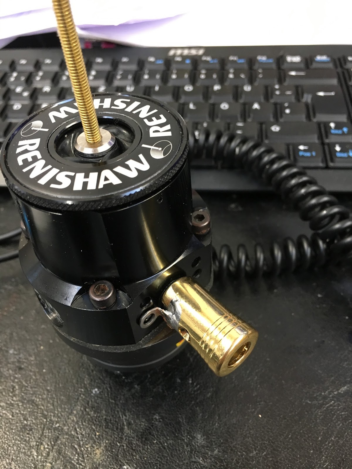
Best thing to do straight away is to strip it down and see what's going on in there. The top plate is a ground steel insert within a brass cap. The description claims this steel is hardened, which is what you'd want / hope to see. Whether or not it is hardened may be another matter. The shroud is made of loominum and is held in place by the brass cap. Once the cap is screwed down, it is locked with 3 tiny grub screws. There is much use of the aforementioned sealant. It actually looks reasonably constructed. Bottom line for me is whether the touch off process is consistent though....


Mounting: 

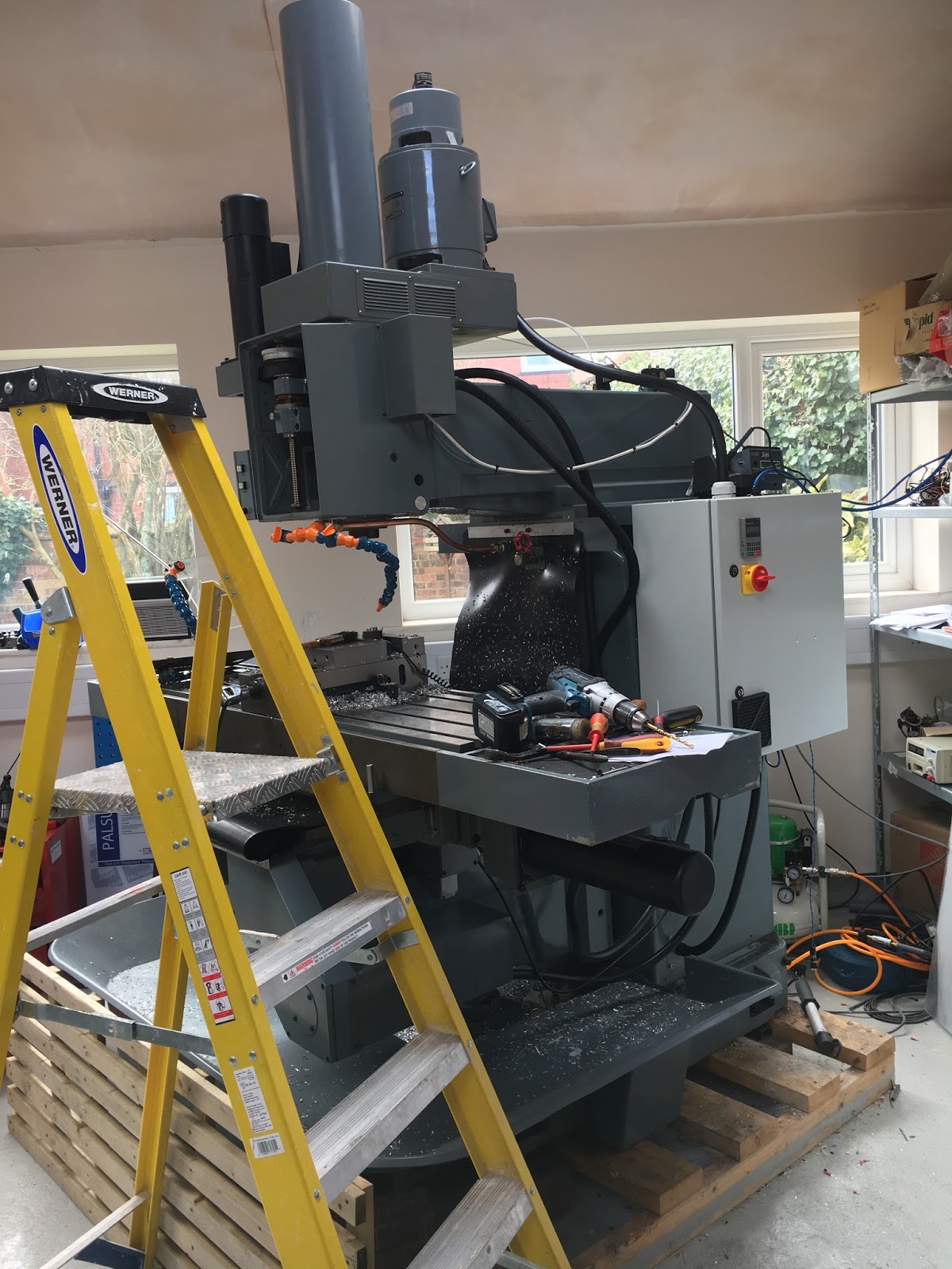
Made a small loominum strap to hold the setter in a fixed position on the table. It is now hard wired so that I can't forget to plug it in before tool setting, given that the tool detection feature doesn't work on this Centroid system (grrr!).


Here it is in action. Actually works pretty consistently. The cable is taken in through a sealed cable gland, although the flexible conduit is almost certainly not waterproof, so I will have to take care to prevent coolant running back up the conduit into the cabinet. To this end, the cable enters from below.


Setting up:

Set up the automatic tool setting parameters so that the fixed coordinates of the tool setter are used when the procedure is called on

  • Set parameter #17 to "3"
  • Go to Setup > Part > WCS Table > Return and enter the coordinates of the tool setter in one of the "Return" positions. I chose G30 P3, having already set G30 P4 as the approximate position of the machine vise.

That seems to work ok. To automatically set the reference tool (T10 in my case), you do this:

Setup > Tool > Offset Lib > Zref > Auto

The tool then moves above the setter and touches off. Then the Z offset of the reference tool is saved as the reference length.

Note that this probe is NC contacts ie opposite sense to my home made tool. Changed the polarity of the signal from "NC" to "NO" (yes, Centroid's definition is different from mine, as previously noted).

Test results:

I didn't do any statistically significant analysis but after 6 readings I get the impression that it's fairly consistent:
  1. -98.6925
  2. -98.6900
  3. -98.6900
  4. -98.6900
  5. -98.6875
  6. -98.6850
Obviously the last digit (0.5um!!) isn't in any way meaningful. But it looks as if we have something like +/- 2.5um or so. That sounds ok, as I wasn't expecting or needing much better.

Conclusion:

Early days yet but so far so good. Certainly better than my home made toy and being hard wired, I've got round the bug in the Centroid software.

Wednesday 28 March 2018

Centroid's macro language

There's a reasonably comprehensive manual for the "M Series" operating system, currently covering "CNC11" ie version 11v3.16. They haven't round to issuing an update for CNC12 but it sounds as if the changes are fairly trivial. Would be nice if they got around to the update....

In order to implement my clever(?) plan to automatically select the correct gear range for the next anticipated spindle speed, I need to be able to read and manipulate various variables such as the demanded spindle speed (as set by the "S" command such as "S3000" for 3000rpm), the current gear ratio etc.

The macro language, like the "PLC" language appears to be of Centroid's devising. It bears some resemblance to the likes of Fanuc / Fadal / Okuma etc but none of those flavours are quite the same as Centroid's.

Section 13 of the manual covers M codes (macros) and there is other pertinent stuff in chapters 14 (many of the common parameters are listed and described there), chapter 11 (variables and "advanced macro statements") and chapter 12 (G codes).

As ever, there are quite a few gaps but of course the author(s) knew what they were talking about even if the reader may not. 

  • There are myriad variations on the "spindle speed" eg demand, actual, limited, overridden etc etc. Which one do you want? And it depends which side of the various reduction gears you are on. Again, the coders knew what they meant.
  • How do you specify the variable you want to access from within a macro? The various industry standard syntaxes don't seem to be followed.
  • There seems to be a difference in what you are able to implement inside a "custom macro" and a normal "macro". That needs to be figured out.
  • There seems to be no means of displaying messages during execution. For debugging, it would be handy to be able to see the values of variables, using something like "print (to display), "output" etc but there's no mention anywhere. Seems I will have to write to a data file instead.
Some simple tests so far:

This is a simple macro that sets the spindle speed at 500rpm, enables the spindle, captures the value of variable #4119 (the demand speed set by the "S" command) and stores it as variable #100, then changes the speed to 500rpm (it doesn't need to issue an M03 as the motor is already running), then finally opens the data file "muzzer.dat" and writes the values of #100, #101, #4119 and #25009 to it.


S500

#100 = #4119
M03
G4 P1
S400
#101 = #4119
G4 P1
M121 "c:\cncm\muzzer.dat"
M123 P#100; #100
M123 P#101; #101
M123 P#4119; #25009


The output (the contents of the file muzzer.dat) is very simple:


 500.000 #100

 400.000 #101
 400.000 #4119
 400.000 #25009


It's a start.

NB: note that the M123 command appends the new data and it also creates the file if it doesn't yet exist. You can delete the contents and save if you want to start again.

More grumblings about encoders and Centroid's rigid tapping - and some cockery

This is heading for the rocks. So far I've failed to find a simple solution to gear range selection (ongoing) and probing (try to use a probe and a tool setter together on the Acorn) and despite connecting up the encoder yesterday, it seems that rigid tapping is no closer.

The main bugger is that they only cater for encoders that are mounted directly on the spindle. And they seem to have designed(?) the rigid tapping software so that it requires a very high encoder count per pulse (CPP). The CPP for a 2 channel encoder is 4 times the pulse per rev (PPR), so my 2000PPR Omron clone is 8000 counts per rev. They are adamant that my 192 count signal, derived from the 48t spindle-mounted bull gear is way below the required minimum count. The index signal seems to be essential too, just to further complicate matters.

As you can see, there is bugger all space in there to get a toothed belt out to an external encoder. The large bull gear is the only accessible part that is directly splined to the spindle itself.


This is what I came up with back on 15th Jan this year. Worked nicely but it seems Centroid require significantly more CPRs.


Funny thing is that Steve Blackmore managed to achieve multi start rigid threading on his lathe with only a single slot encoder (see the bottom of this page). That was using the turning version of the very same Newker 990 controller I have just removed from my machine. Part of the reason for doing that was to achieve rigid tapping. What have I done???

Here's what Steve managed on his first trials:


I seem to have established beyond any doubt that Centroid can't support a motor mounted encoder and they seem equally adamant about the encoder count. I can't really believe that they act on each encoder count, given the likely thread time in the controller. I wonder if it's worth connecting up my gear tooth encoder through the differential line driver and seeing what happens. As a second line of attack, I wonder if it would be possible to increase the effective counts per rev by triggering a burst of pulses from each transition, to fool the controller into thinking that it was seeing a high count encoder signal. Sounds tricky, given that the phasing must remain correct so that it can deduce the direction of rotation.

Apparently that cock Elrod came up with a product (described as a "rigid tapping adaptor") that allows you to mount an encoder alongside the head of a Bridgeport and drive it with a toothed belt. As you might expect from the guy, he claims to have found something to patent in the process. Think about it - use a belt to drive an encoder from the spindle. Sounds like a patent worthy result to me. I used to joke that you could patent a glass of water in the US and it sounds as if I wasn't far off there. Take a look at the patent - 2 pulleys and an encoder. What a joker.

Tuesday 27 March 2018

Omron encoder on spindle motor

I ordered a Chinese clone of an Omron encoder from ebay on 16th March. It arrived yesterday (26th) which was pretty quick, given that it came from China so it seemed rude not to get on and fit it. Not bad for £20 or so and certainly a lot less than a genuine Omron part.


It would seem rude not to remove the cover to see what has been going on in there.


This is the PCBA. The differential line driver is a TI part AM26C311. It's similar to the part I bought to make my own. Looks likely to be a fairly accurate clone of what I'd imagine the original looked like. Probably the result of running off an unscheduled extra batch of products in the approved factory and them getting rerouted on their way out of the factory.


I'd already established that there wasn't much chance of fitting it to the spindle, so instead I focused on connecting it to the spindle motor. There's already a spindle brake on the top of the motor and I'd rather not lose that in case it is helpful for locking the spindle during tool changes etc.


It got a bit rusty during its time on my building site(!). The whole top part rotates with the spindle, so those six M3 screws could come in handy.


Some quick measurements and sketches. At this point, all sorts of machining operations come to mind. But I'm a lazy bastard as well as a fat one, so I think carefully about how to achieve maximum outcome with minimum effort. My solution is simply a piece of 1" loominum bar with 3 holes in it - the centre one tapped M5 and the outer holes being M3 clear.  Simple - and quick.


Yes, it's quite a way up - I'm standing on the machine table which is over 1.1m from the ground and it's almost at head height.


The M5 bolt, turned down to a convenient 6.0mm diameter has a 60 degree point, so it locates conveniently in the centre hole on the end of the motor shaft, aligning the part. I can adjust it carefully so that the bracket is aligned - without the bracket sitting proud of the shaft surface. The DTI showed that after setup it was concentric to about 5"', which is fine - I'm sure the plastic Oldham coupling that came with the encoder won't be anything like as good as that. 


Bang a 16mm hole in the cover to clear the Oldham coupling:


The encoder isn't mounted yet but you can see the plan coming together:


Here it is with the standoffs fitted and the encoder aligned concentric with the motor spindle:


I ran the screened encoder cable down the motor conduit. It was only just about long enough at 2m. That required me to solder the 9 way D connector on in situ


It just reaches the encoder connector on the Acorn board. Not absolutely ideal but I've done a lot worse on the bodgery front:


Job done - and it works. Of course, the controller is expecting the encoder to be a spindle encoder, not a motor encoder. But either way, it won't do rigid tapping without an encoder.

If the controller can't be configured to take this as a motor speed signal, perhaps I could divide the declared encoder count by the gear ratio (about 0.167) and only enable it for tapping. We'll see - but getting answers out of the Centroid team is like drawing teeth....

Friday 23 March 2018

Wire up gear selector solenoids and gear range status switches - and set up gear parameters. Success!

Sod it. Let's just wire up the solenoids to the 2 spare relays, connect the high and low microswitches to 2 of the remaining 3 inputs and see where that gets us. The Centroid "support" is very terse ie almost nonexistent. I suppose that's to be expected, as we are hobby users and they make their money from the professional users with the proper purses.

I have a 24V PSU of about 20W (I'm not certain which model I bought now and the part number label is buried) but currently it's only driving the soft start relay which must be taking sod all current. I can't be arsed to check back for either the PSU or the relay ratings but I'm pretty certain I have spare capacity. It's independent of the main Acorn system, so the worst case (over)load situation isn't going to damage anything.


So - status microswitches wired up thus (closed when that range selected):

  • Common (ground) - green
  • High range - orange
  • "Medium" range (my low speed) - red
And solenoid connections:
  • O/P 1 - yellow (low speed range)
  • O/P 2 - pink (high speed range)
  • Ground - green
Here's how I configured the IO using the wizard:


And the spindle settings:


I swapped the "Mist" function back and forth between OP1 and OP2 using the wizard, then manually enabled the mist button in the VCP display. There was only one such function button on the VCP that could be quickly configured using the wizard, hence the reeated use of the wizard.

Pressing Alt-I shows the status of the inputs and outputs, so it's easy to check it's all doing what it should.

High range, with O/P 2 and I/P 2 high (1170rpm):


Low range with O/P 1 and I/P 1 active (234rpm):


That works - and the spindle does actually spin in the correct range. 

NB: In the wizard I set the gear ratio in the low range as 0.2 for now, until I look back and calculate the correct ratio. Sure enough though, when I change the ratio it knows and changes the displayed set point accordingly. I guess that if I demand a spindle speed that exceeds the allowable range it will complain. And vise versa. I'll check tomorrow.....

The gear ratio numbers were noted back in January. In summary,

First reduction stage input gear - 23t
First reduction stage output gear (Tufnol) - 64t
Second reduction stage input gear - 22t
Second reduction stage output gear (on spindle) - 48t

Overall ratio: 64/23 x 48/22 = 6.07:1


The Centroid parameter required is the inverse of this, ie 

0.16471354166666666666666666666667

I think we can safely round this down to 4 significant figures, ie

0.1647

Next - try to figure out how to modify the M3 macro (and then copy over into the M4 macro) to automatically switch the solenoids over (with the spindle stopped!!)
then start the spindle. That will be a little more challenging.

Custom macros for the Centroid Acorn

My machine has 2 speed ranges and a proper variable speed motor / VFD. On the original system, the high speed range was 1000-6000rpm and the lower range was something like 20-1000rpm. Unlike the Bridgeport arrangement with its combination belt / gear drive, the two stage gear reduction does not cause a reversal of direction between ranges. That's an improvement to be thankful for.

The gear selection mechanism uses a rotary pneumatic actuator to shift ranges and I'd like the range selection to happen automatically. There are 2 spare relay outputs on the Acorn, so I should be able to drive the (24V) pneumatic solenoids with them, assuming I can find enough current in the existing power supply - or add another one if necessary.

It looks as if the M3 and M4 macros are easy to customise but it becomes rapidly clear that the whole software thing is going to be a bit of a challenge. They talk about 2 main software elements - the PC-resident "CNC12" (user GUI and top level controls) and what they like to call the "PLC" software which appears to reside in the Beagle Bone Green (the brains of the actual Acorn unit). I have no idea why they call it "PLC", as there isn't a PLC to be found. And even if they were using a high level (text) programming language to implement a PLC-like environment, that would normally be a version of Pascal. The Centroid language is nothing like that. Looking at the PLC "compiler" program that was installed when I loaded up their system, it seems they developed their own compiler, so presumably they have also made up their own syntax, acronyms, conventions etc.

The previous products (currently the "Oak" and "All In One DC" seem to use a DSP (TMS320 perhaps?), which is a long way from being a PLC or an FPGA. However, there appear to be several large packages, so I wonder if one of them is an FPGA or CPLD.

I'm realising that the gear "control" is passive on the Centroid by default - in other words it likes to be told what gear it's in (using an input), rather than be the daddy and actually select the correct gear. That's a bit shit in a computer controlled machine. Anyway, let's live with it for now...

Sunday 18 March 2018

...but insurmountable (for now) problem with tool touch probe detection. Bollocks.

What a lark!

Hmmm. I seem to be playing a guessing game. The software guys who configured the "PLC" logic in the Centroid system knew what they wanted it to do and described it as they saw logical. However, things don't quite work out so logically if you are The Fat Bloke sitting in my workshop.

Take as an example the "probe detect" input. That's a loop back connection that pulls the "probe detect" input down to ground when the probe is plugged in. It can be used to detect if the probe is present - or more importantly if it is missing - to prevent you trying to touch off your expensive tooling against a disconnected tool touch sensor.

When the tool touch sensor / tool setter / whatever touches the tool, it pulls the "probe triggered" input down to ground. My touch sensor is pretty much like the Centroid TT-1 "mechanical" device, so I'll refer to that from now on, for simplicity.

So that's 2 inputs that need to be pulled down to ground. Given that all the 8 inputs have pull ups (to 24V), you can only attach switches between the input and ground. So should the "probe detect" input be described logically as "normally open" (NO) or "normally closed" (NC)? Depends if you think you are trying to detect the presence or absence of an external circuit. That one kept me guessing for a while....

Problem with parameters for work probing and tool setting:

Seems there is an issue with the software when you try to fit both a TT (tool setting sensor) and a touch probe (like my Renishaw). There is a "spindle lockout" function that looks at the "probe detect" input and stops spindle operation - and also inhibits probing if there isn't a probe tool fitted. However, if you get it working for the probe tool, the tool setter detection doesn't work. WTF?? 

Looks to me as if there is a logical issue that Centroid need to look into. For now almost everything works, although I will need to be careful if I use the automatic tool length measurement function, as it can't tell if I have actually plugged in the tool setter. The jog rate will also be limited due to the system somehow thinking there's a probe fitted. 

Rather than repeat everything chapter and verse, here's the post I made this afternoon on the Centroid Acorn user forum:


Hi Keith (and thanks, Fredsan)

I've spent several hours looking at this now, testing all the possible permutations and combinations of the relevant parameters. I think the situation is now fairly clear, having proved each setup to exhaustion and beyond.

The problem arises with the probe detect function, which I think explains how Fred hasn't seen an issue. If you have the tool touch probe (TT) hard wired, you don't need to do a probe detect on it. In my case, I have a pluggable TT probe, so I want to detect if it's present before sending the tool towards it(!!).

The problem seems to be that if the probe detect input is triggered by connecting the TT probe, the tool length search function doesn't work correctly - it gets confused and thinks the tool signal is active even though it isn't. The result is that the quill retracts, which isn't very helpful. It's not a matter of correctly configuring the parameters, as I have them working for the touch probe.

The solution for me (for now) is to leave the TT detect wire disconnected. That way the TT tool length probe function works correctly. The downside is that the controller doesn't know if the TT is actually plugged in and I could run the tool into my TT. The other issue is that somehow the controller believes that there is a probe permanently plugged in, so I get a "453 jogging while probe detected" whether it's plugged in or not.

The other related issue is that although my Renishaw probe functions fully with the various probing operations - and the system will only probe with it plugged in (which is very good) - the "453 jogging while probe detected" message goes away when I plug it in.

My parameters are like this:
#11: -4
#18: +6
#44: +7
#257: -6

Yes, parameters 18 and 257 are opposite polarity(!!). My probe signal is input 4, detect input 6, TT signal input 7.

I'm pretty certain there's a logical error somewhere in the software. One solution for me would be to hard wire the TT and fix it on the table but that's not ideal and it won't get rid of the "jogging while probe detected" message. Presumably that's also limiting my jog rate.

I've attached my current report if that will help.

So at least I can set up my tool lengths automatically now and the touch probe works safely. But hopefully this TT detect issue can be fixed too.

Pleased to report that everything else seems to be working nicely. Very pleased with the conversion so far!

Murray


But at least I have my touch probe working (safely!) and the automatic tool setting function works, even if I have to take care to ensure it is plugged in first....

You'd have thought (hoped?) that the spindle wouldn't work if it thinks there's a probe fitted. But it seems happy to air cut my current file. Even though it claims there is a probe fitted when I jog (there isn't).


Saturday 17 March 2018

Probing function working!


The cable is wired up now.

Completed, along with 3.5mm stereo plug:


The toolholder that came with it is BT40 but my machine requires ISO40 (INT40) ie requires the addition of a shank / collar. Luckily I have one left over from the last time I converted some toolholders. The M16 bolt is screwed into both the holder and the collar. 


To weld these together, I ground a couple of slots (on opposite sides), then used the TIG welder to finish the job:


Here we are - all finished:


This screenshot shows the parameters as currently set. The key parameters are 11 and 44, which define the input channels for the touch probe and tool setting (touch plate) devices:


I've tried to set the machine up to use both the touch plate AND the touch probe. They need to have different sockets so I've now changed the plug on the probe to a 5 pin DIN style to prevent me plugging the wrong device in to the appropriate socket.

Fredsan on the Centroid forum showed how it was possible to get both working together, albeit with different input channel numbers.

So far I have the touch probe working but the tool setter doesn't play with the automatic tool length function. Have I messed up one of the parameters or got one of the inputs inverted? Need to mess about a bit....


Friday 16 March 2018

Automatic tool length measurement and Renishaw touch probe

Tool Touch Probe:

I connected up my home made Tool Touch Probe that senses when the tool makes contact. It can be a pretty simple design on the face of it but the main complication is the need to spring load the touch surface. If you use a rigid touch surface and send a carbide tool into it, you will chip the edges and bugger the tool. On the other hand, you need to ensure the spring loaded touch surface returns consistently to the same position every time after being depressed by the tool. So you need a reasonably flat and free moving pair of mating surfaces within the assembly. In mine, I have a simple spring loaded plunger and a Turnol body.

I made the thing a few months ago but it needs some modifications to work with the Centroid controller:
  • The Centroid wants to see a loop back circuit to tell it that a touch probe has been connected. That allows it to control the search speed - and it also prevents you from trying to detect a tool when the probe hasn't been plugged in. You could easily send the quill into something unforgiving in that situation.....
  • The standard wiring arrangement for the Centroid TT-1 Tool Touch Probe uses a 3.5mm audio plug (cable) and socket (probe). But they have chosen to use the shield / external housing for the touch surface connection. That's a complete PITA for my machine, as most 3.5mm panel mounting sockets have a grounded shield by the way it's mounted on the panel. So I changed the connections around. It's not going to be a big issue, as I won't be interchanging my probes with genuine Centroid ones. Mine is connected like this:
    • Probe signal - tip (blue)
    • Probe detect - ring (green)
    • Probe ground - shield (black)
  • So I had to rejig the internals of my tool touch probe. TBH, that made a bit of a mess of what was otherwise a neat and simple solution. But It'll do for now.....
I discovered that if you try to send the table or quill to the extremes of travel before you have homed the machine, the limit switches don't function as limit switches. Hmmm, perhaps I'm missing something. This needs closer investigation.

Here are the component parts - insulating body (Tufnol), steel touch surface plunger thing, steel spring (a coiled up length of stainless steel TIG welding rod) and a 3.5mm audio socket:

No, it's not pretty. The socket and an M6 screw hold the spring in place.


Looks OK from the outside:


But it's a pig's ear inside. My excuse is that "I will tidy it up later once I know it works". That old chestnut. The body of the socket has to be insulated from the spring, the spring has to be connected to the "tip" contact and the "ring" element has to be shorted to the "shield" ie body. Luckily you can't see this mess from outside unless you pick it up and stare up its backside.


Plugs into a socket on the cabinet:


Here is a short vid showing it in action:


The tool lengths returned over 8 consecutive tests were all either -152.857mm or -152.863mm. That's 6um difference, which is a bit odd. With a 5000um per revolution ballscrew and 2000 pulses per rev, that's 2.5um per step - not 3um or 6um. I suspect some form of imperial measurements actually happening under the hood. But quite why I see a 6um step (ie not a 3um step) is unclear at the moment.

The "-153mm" refers to how much shorter the current tool is relative to the reference tool. However, if you have not homed the machine yet, I suspect it assumes that spindle top (home) is zero position with the reference tool fitted. As my quill has a max movement range that is not much more than 150mm, clearly it has lost sight of the fact that my reference tool was set at around 100mm yesterday.

Renishaw probe:

Now onto the butchered Renishaw MP1 probe. I need to stop the connector being pulled out, so I have used my tinkering skills(?) to solder a small ring crimp onto the brass body of the 5 pin DIN connector. It's a pretty shitty quality connector but will also do for now. The loop back and probe signals will happen here, inside the cover.


So now I will need to find a 3.5mm cable and solder it onto the pin assembly. Then see how badly I can bend the probe...

Note the brass screw currently fitted in place of the ceramic / sapphire probe tip. I will break that later once everything is up and running.


Thursday 15 March 2018

Heheh first air cuts on The Shiz with new Acorn system

I reposted one of the operations from my X axis bracket using the Centroid post processor. I chose the first 3 sections - Face, 2D Adaptive (roughing) and 2D Pocket (finish). Seemed to post OK.


First issue - the free version only supports up to 50kB file size. But even removing 2 of the operations still left it too big. Sod it - I was planning on paying for the upgrade to "Pro" or "Digitising" pretty soon anyway. And as it seems to be working quite nicely, coughing up seemed the sensible thing to do.

I went for the "Digitising" option ($399 = £299), as I intend to use my probe and make the best of the fancy probing functions that Fusion 360 supports. The digitising option also allows you to do 3D digitising of objects (to generate an STL file) - the clue's in the name - although I don't expect to make much use of that. Who knows, famous last words etc. The other option would be the cheaper "Pro" upgrade which only supports simple probing (edge and hole centre) and is limited to 10 tools. But here doesn't seem to be a way to upgrade from Pro to Digitising, so it's probably best just to go the whole hog now and be done with it.

The various options vs features (and prices!) are shown here

You send them a config "report" for your system and they send you back a license key for your particular Acorn. Then you go into the utility menu and point it at the license file. Worked OK.

Here's my first program, using the code generated above:


And the whole sequence, from powering up the cabinet, through homing, to cutting the (air) part:


Have to say,  the homing speed is PAINFULLY slow. I had it set to the maximum configurable speed. Thank god it's not a large gantry machine or I'd have had to go off and make a cup of tea / take a crap / walk the dogs.

Annoyingly, the Acorn doesn't remember where it was when you turned the power off. The Newker had a non volatile memory, so it wasn't necessary to home each time - that worked very nicely. Dunno if this is a limitation of the Acorn or simply that they chose not to allow it but that could be a right PITA. I'll probably end up rapiding the table to the far ends before either turning off or homing.

Before I actually cut any metal, I need to figure out how to work the tool length setting function. Ideally I'd use the tool setting gauge to do this automatically. 

Wednesday 14 March 2018

Acorn conversion 95% complete - configuration settings - The Shiz lives again!!

Up and running:

The transition from Chinese controller (Newker 990MDb) to Centroid Acorn is almost complete. Seems to have gone pretty smoothly. I've pretty much connected up and commissioned most of the system now:
  • All 3 servos connected up to motors and system configured to suit. Started out with 60V / 5A from bench PSU until I'd checked that the servos were connected up correctly. The Y axis armature connection was initially arse about face.
  • Limit and home switches wired up. The +L and -L for all axes are wired together into one input. The home switches are wired into another input.
  • Power drawbar / VFD interlock / quill top switch commissioned. The impact driver will only operate if the VFD is stopped and the spindle is at top position.
  • Coolant pump (SSR controlled).
  • Lube pump (co-wired with lube pump - powered continuously when cabinet isolator in on position). The Bijur pump automatically delivers a stroke every so many hours of operation - no need for the controller to get involved.
  • VFD FWD / REV / speed / spindle stopped etc. All working nicely.
  • Cabinet cooling fan wired up and running.

  • Probe detect and input. Ready for me to finish messing with the Renishaw probe.
  • Spindle encoder cable run into the cabinet, ready for driver circuit. 
Runs the example programs OK - table movements, spindle rotation, soft and hard limits etc. I need to post process one of my previous jobs using the Centroid post and see how it works out....

    Some things still to do:
    • Spindle encoder requires differential driver. Need to make interface circuit.
    • Probe testing etc.
    • Spindle range selection??? Needs some thought - either learn about PLC programming or use a manual selection with a status input 
    Configuration settings:

    Here's what we have today:


    Lube pump connections: 

    Here's the lube pump with the wiring cover removed. The 2 black wires are (presumably) for the float switch. I won't be bothering with that. The synchronous ("clock") motor and gearbox controls the frequency of stroke delivery


    Heheh

    Tuesday 13 March 2018

    Repairing the braking module

    The components for the braking module repair arrived yesterday from RS. I'm going to replace most of the semiconductors, given that they are pretty cheap and I don't want to be having several goes at repairing the damned thing.

    Here we are. All built up with new compts:


    This piece of copper wire bridges the blown off track on the top side:


    This is the top side. Yes, I checked it worked  with a bench PSU.


    Finally assembled onto its baseplate:


    And slapped back into the cabinet:


    Hopefully that's the end of that.

    Final assembly and test of the spindle nose adaptor - RESULT!!

    After the recent distraction caused by the 3D scanner, resurrecting the 3D printer and buggering about with the throttle bodies for my Honda...