Monday 31 December 2018

Machining the acetal tool tray

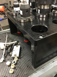
Machining the tray - swarf time!!:

There comes a time when you just have to press the button and let it do its thing:

Outer profile - 2D Adaptive and 2D Contour:


Roughing out the bores:


Using a ball end mill to create the tapers:


Not bad: 


Chamfering bores and outer profile:


Job done, bar a bit of deburring:


Happy with that:


My main impression - that was damned slow. I was expecting to be shifting a lot more swarf a lot quicker. I think I can safely up the chip load (mm/tooth) from its 0.05mm to something a bit more serious. Admittedly a single flute cutter is going to make fewer cuts per rev than a multi flute cutter but what's the point in having a large flute if you don't make full use of it to shift proper swarf? Next time.....

Machining the legs:

The final part(s) were the 2 "legs" to hold the tray off the deck. Not worth buggering about with Fusion 360 when it's a question of squaring off some simple rectangular stock to size and drilling 4 holes in each. With the wireless MPG pendant and the DRO display (which is duplicated on the MPG itself), it's a simple matter of squaring off, measuring it up and then incrementally adjusting the overall dimensions to get to the final size.

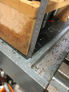
I just used my 18V cordless circular saw to chop a couple of pieces off the big piece. The finish wasn't too bad but it's far from flat:


With APGT1604 polished inserts in the Korloy face mill, the finish is pretty decent:


Manual operation using the DRO is pretty effective. I'll settle for that:


As for the holes, I could simply have drilled them manually, positioning the holes using the DRO but this seems an ideal opportunity to get into the "canned cycles". A quick 2D drawing gives the critical dimensions:


Using the "array of deep drilled holes" function, I flashed up the required g code. As I have cleverly arranged for the holes to be unevenly placed for some reason (no idea how that happened), it's actually 2 sets of 2 holes per leg. 

By placing the 2 pieces back to back in a mirrored arrangement, the rows of holes are 15mm apart and all 8 holes can be made in one go:


You firstly add the tool number, drill size, speed, feedrate etc, then the actual operations using that drill are specified on the following lines. 

Here's the whole operation in its entirety:


The "deep drill" operation retracts the drill fully after each peck to clear the swarf.


 Here is what you see if you ask for the graphical view:


With the correct tool loaded, you need to set the X, Y and Z positions in G54 (using the "zero axis" function), then off you go....

Used a collet chuck to minimise stickout.


Manually tapped the M6 holes (well, using a cordless drill) and used the belt sander to fillet the remaining edges on the legs so that almost blend with the main tray body/

The bottom line:

Here's what we've got finally:


Happy with that!

Acetal tool tray - CAM!!

Finally got enough time away from tiling, grouting, overeating, taxi driving and endless buying to get some time in the workshop. The piece of acetal stock has been on the table of The Shiz for a few weeks now and I've been itching to get machining.

Here's the toolpath(s) generated in Fusion 360. The 240 x 240 outer profile is roughed out from the 250 x 265 stock with a 2D Adaptive, then 2D Contour to finish it off. Then the 9 bores are opened up with a 2D Profile (no pilot drill, just spiral in) using the single flute end mill. The parallel bores are then tapered using a 10mm ball end mill. Finally, the top edges are chamfered using the trusty old 1/2" tool.


ncviewer seems to like what it sees:


And the graphical preview in CNC12 seems to agree: 


Was a bit confused with the "T8" entry in line 2626 etc. I need tool 19 for the upcoming operations, so why the "T8"? In fact, this is simply telling the ATC (if fitted) that the next tool will be T8 so it can get on and preload that tool ahead of the next tool change. I think it is actually associated with the previous "M6" command which is . 


You can see why I might have been confused by the CNC12 screen:


It shows T8 H19 when tool 19 is in use. Of course, it doesn't really matter, as the control point has been calculated by the Fusion post processor on the basis of the dimensions of the tool previously selected. The tool length offset is then what matters most and that's shown as H19 which is as expected. This is presumably how tool information is traditionally displayed....

Next - get swarfing....

Friday 28 December 2018

Centroid Acorn v4.12 parameters - finally sorted

Yes, I did my last proper machining on The Shiz back in late April (27th) when I finished off the Z axis yoke. Since then I've been focusing on finishing off the Bridgeport conversion and in the event it hasn't required any further CNC work yet.

So when I came to flashing up The Shiz today, I hit a brick wall again. Last time round (a couple of weeks ago) it was down to some changes in the Windows Defender Firewall preventing the PC ("CNC12") talking to the Acorn (Beagle Bone Green). Everything else seemed to be working fine. This issue only became apparent when I actually tried to power up the spindle. I was planning on manually drilling out the 8 fixing holes (counterbored M6, to take cap head bolts) as a cunning way of holding the stock down, as otherwise it was looking a little tricky. But when I tried to turn the spindle on, I got a "probe present" type error. This is to prevent the Stupid Fat Bloke accidentally spinning the spindle with the Renishaw probe fitted, which wouldn't end well. 

Sure enough, although I'd tried out many of the functions such as the tool setting and probing functions when I was getting the new 4.12 release back up to a working state, it's clear that I hadn't actually tried cutting air, as in spinning any sort of tool, even an imaginary one.

The most obvious issue is the function that uses the probe detect input to inhibit the spindle. Sounds simple enough but the various / myriad inputs are gated together in a mysterious and undocumented fashion. The partial documentation that does exist only gives away part of the workings and to be honest I'm not convinced anybody at Centroid fully understands it. I suspect the originators have left / died / forgotten how it is constructed, so each time they go in to make changes it becomes more and more fraught.

Last time (back in April) I posted what I thought to be the definitive config on the Centroid forum, this is what I said:

Inputs and settings:
* Renishaw probe trigger goes to input 4. Described as "Unused" and "NC" in the wizard. It's normally closed, so contact opens the switch and the input is pulled up to 24V.
* Renishaw probe detect goes to input 6. Described as "ProbeDetect" and "NC" in the wizard. It's a simple loop to ground inside the plug.
* TT trigger signal goes to input 7. Described as "ProbeTripped" and "NO" in the wizard. My probe is also a normally closed electrical switch, so contact with the tool lets the input signal go up to 24V.

Parameter settings:
* # 11 is "-4" (TT to input 4, the sign indicates the type of input, NC or NO)
* # 12 is "10" (the tool number of the Renishaw probe in the library)
* # 17 is "3" on my machine (represents "G30 P3" command). The P3 coords are stored in the WCS table / return table. The coordinates define the position of my (fixed) TT. It rapids there before doing tool measurement with the TT.
* # 18 IS NOW "-6" (changed in 4.12). The input that is checked to see if a probe is connected. If so, the spindle is inhibited.) NB: You should also set #257.
* # 257 is "+6". Yes, NOW POSITIVE six (changed in 4.12). "Tool touchoff detect". Parameter #18 requires this test for the Renishaw probe but you have to fool it for the TT probe.
* #43 is 2 ("use #44 defined input for TT")
* #44 is 7 (TT input channel number)

It's now clear that some of this is bollocks (given that the spindle won't even turn) and looking at it, anyone can see the description of parameter # 257 is wrong. What a dork.

After that half-arsed attempt to show how to get a TT and probe to co-exist on an Acorn system, a guy called swissi made a decent pass at it in September. His notes tell you how to correctly choose the options within the Centroid Setup Wizard to get the required config setup. I have to say that even after following that carefully, it still didn't work. Finally, I managed to figure out and frig the required changes.

This is actually the correct config:

Inputs and settings:
* Renishaw probe trigger goes to input 4. Described as "Unused" and "NC" in the wizard. It's normally closed, so contact opens the switch and the input is pulled up to 24V.
* Renishaw probe detect goes to input 6. Described as "ProbeDetect" and "NC" in the wizard. It's a simple loop to ground inside the plug.
* TT trigger signal goes to input 7. Described as "ProbeTripped" and "NC" in the wizard. My probe is also a normally closed electrical switch, so contact with the tool lets the input signal go up to 24V.

Parameter settings:
* # 11 is "-4" (TT to input 4, the sign indicates the type of input, NC or NO)
* # 12 is "10" (the tool number of the Renishaw probe in the library)
* # 17 is "3" on my machine (represents "G30 P3" command). The P3 coords are stored in the WCS table / return table. The coordinates define the position of my (fixed) TT. It rapids there before doing tool measurement with the TT.
* # 18 IS NOW "+6" (changed in 4.12). The input that is checked to see if a probe is connected. If so, the spindle is inhibited.)
* # 257 is "+7". Yes, NOW POSITIVE seven (changed in 4.12). "Tool touchoff detect". 
* #43 is 2 ("use #44 defined input for TT")
* #44 is -7 (TT input channel number)

I suspect the issue was around parameter #18, as the other changes relate to the TT (tool setting) probe.

But what a wanker getting that wrong - and not even noticing it for 6+ months. So now I've actually tested:
  • Tool setter / tool offset measurement works with the TT.
  • Part probing works with the Renishaw probe.
  • Probing won't start without the probe fitted.
  • Spindle won't turn with probe plugged in.
  • Spindle actually turns when told to(!)
And I've created a backup file ("report") so I can revert again if anything screws up ie The Stupid Fat Bloke gets his podgey fingers on the config.

I thought for a moment that I no longer neededed to plug in the dummy connector when the probe tool is not plugged in but that turned out to be optimistic. Leaving the dummy unplugged prevents fast jogging and also stops MDI moves. Doh.

What a waste of time - about 4 hours or so trying to recall the whole sorry saga, then attempting to fix the problem. But at least now I may be able to do some hole drilling....

Wednesday 19 December 2018

Acetal speeds and feeds for tool tray

Where to start?

It's hardly rocket science but there doesn't seem to be a clear consensus on speeds and feeds for milling acetal. Much of the problem is that quoted feeds and speeds for plastics seem to default to acrylic, not acetal.

From APT-Tools:


According to APT, for acrylic you can feed a 10mm single flute cutter at 2400 mm/min at 8000rpm. That's 0.3 mm/rev for a single flute cutter. Wow. That surface speed comes out at about 250 m/min....

From Cutwel (YG):


This seems to agree with APT - and again relates to acrylic, not acetal. 

From plasticshop


They actually give data for acetal. In terms of feeds, they speak of <0.05 mm per tooth. At 6000rpm, that's 300 mm/min, which is some way short of 2400 mm/min, like a factor of 20:1. Certainly, I can imagine cutting at 0.05 mm per tooth, whereas 0.3 mm per tooth is hard to imagine. Although APT are talking about acrylic, not acetal, I hadn't realised there's quite that difference!

Boedeker Plastics Inc:


The figures from them seem to agree with plasticshop, albeit in Imperial units. However, their recommendations are 270 - 450 sfm (80 - 140 m/min) and 2 thou per tooth (0.05 mm per tooth). That is reassuring.

Finally, for drilling, Boedeker suggest about 0.02" / rev for a 16mm drill. That's about 0.5mm / rev and the recommended surface speed of 150 m / min corresponds to about 3000 rpm! That would take some balls.


However, the notes at the top of the page say:

The insulating characteristics of plastics require consideration during drilling operations, especially when hole depths are greater than twice the diameter.

Small diameter holes (232" or 1mm to 1.0 or 25mm) - High speed steel twist drills are generally sufficient for small holes. To improve swarf removal, frequent pull-out (peck drilling) is suggested. A slow spiral (low helix drill will allow for better swarf removal.

Large diameter holes (1.0” or 25mm and larger) - A slow spiral (low helix) drill or general purpose drill bit ground to a 118° point angle with 9° to 15° lip clearance is recommended. The lip rake should be ground (dubbed off) and the web thinned.

It is generally best to drill a pilot hole (maximum 1/2” diameter) using 600 to 1,000 rpm and a positive feed of 0.005” to 0.015” per revolution....Secondary drilling at 400 to 500 rpm at 0.008 to 0.020” per revolution is required to expand the hole to larger diameters.

Conclusions:

For milling, I'll go with 0.05 mm per tooth for the 10mm cutter and although I can't manage more than 6000rpm, that would result in around 190 m/min which doesn't sound silly - so I could actually afford to reduce that. 4000 rpm for the 10mm cutter would give me about 125 m/min surface speed. Doesn't sound silly slow and certainly I want to avoid any danger of melting, as that would surely result in broken cutters.

Note that the feed per tooth seems to be proportional to the cutter diameter, so an 8mm cutter would be good for about 0.04 mm per tooth and a 4mm cutter would be good for about 0.02mm per tooth. Obviously for both of those tools, the machine needs to be running at full speed (6000 rpm).

For drilling, My 6.5mm pilot drill (also used for the M6 clearance holes) needs to be running at about 1000 rpm and 0.25 mm/rev. The 16mm drill should be down at ~500 rpm and 0.25 mm/rev.

Tool table setup for acetal machining:

So finally, the tools, feeds and speeds I plan to use are:
  • 10mm carbide single flute end mill. 4000 rpm, 0.05mm/tooth.
  • 8mm carbide 2-flute chamfer mill. 6000 rpm, 0.04mm/tooth.
  • 4mm carbide single flute end mill. 6000 rpm, 0.02mm/tooth.
  • 6.5mm HSSCo drill (pilot). 1000 rpm, 0.25 mm/rev.
  • 16mm HSSCo drill. 500 rpm, 0.25 mm/rev.
  • 10mm carbide ball end mill. 4000 rpm, 0.05mm/tooth.
Let's set them up, then!

Samsung TV remote control battery cover - MkII

Hmmm. None of the remote control battery covers on Thingiverse are for the exact same model as mine, even though they look very similar.

Turns out the one I made is about 5-6mm too short. WTF? Looked OK but doesn't actually fit. Sod it. Try again.

This one looks better. Flashed one up last night. The old one is on the left and the new one on the right. Odd that the guy who made it used a series of 4 flats rather than create a curved surface. What the hell, it actually seems to be the right size and will be an improvement on what I have(nt) got currently.


Here's my sketch. The overall length of 64mm matches the new part.


There.

Update 1st Jan 2019 - works well, although it would have looked better if the back curved surface had been, well, curved rather than several flats. But it's a good result, so shouldn't complain!


Tuesday 18 December 2018

Enclosure for line driver - Fusion 360 and Cetus 3D printer

Design enclosure in Fusion 360:

Now that I have bodged the driver board together, it would seem rude not to make an enclosure to house it in.


Flash up quick sketch from the PCB dimensions and extrude to create the PCB, then import the 2D view (JPG) from EasyEDA into Fusion 360 and use it as a "decal" to give a visual to the surface of the board. It didn't work out too well, due to the holes in the PCB which resulted in a sort of black hole vortex effect near them.


Import 3D CAD models of almost identical spring terminal 5.08mm connectors from Traceparts like this for the 5-way part. The best format to choose is Autodesk Inventor. Probably not surprising really, given that they own Fusion.


Assemble connectors onto PCB to form a virtual PCBA. 


Then project the outline to create another sketch offset from the bottom of the board by the desired (3mm) clearance. This will form the basis for the main housing. Offset the projected geometry to give some finite clearance (0.5mm all round) and define the positions of the mounting holes etc.


Extrude the profile to form walls and standoffs, then cut extrude at each end to clear the connectors (by 0.5mm or so).


Provide tab feature on side wall to hold PCB down on one side.


They fit together like this:


Project top face geometry onto another sketch plane located on the top surface of the main housing. Then extrude to form a cover and locating tabs, taking care to clear the connector bodies.


Extrude 2 pillars from the cover to hold the PCBA down when the cover is fitted.


Make countersunk holes on either side of main housing to align with holes in the tabs on the cover. This will allow 2 self tappers to secure the cover. I couldn't be arsed to design a spring clip just for this, as I'm only making a few of them.


Goes together like this:


It would look like this if I made the lid transparent:


Just need to make them now.

3D printing the enclosure:

Here we go. Ran the first set over night. The rafts and supports came away easily enough and I managed to only slightly nip one feature with the cutters (the PCB hold down tab). Looks good overall. I used the "fast" setting rather than wait forever for the normal or fine settings. The surface finish is fine for this application:


The PCBA fits very nicely indeed:


And the cover snaps into place:


I'll probably get away without needing to fit the self tappers, as the cover is a snap fit due to the close fit of the rails and pillars with the main housing features. Besides, it will spend its life sitting in a cabinet. 

I'm printing off another enclosure even as we speak. I need one for each of the 2 servo motors.

Bargain buckets.

Monday 17 December 2018

Acetal tool tray - waking up The Shiz - problems finding the Acorn.....

MDF tooltray - not good:

Some months ago I made a simple tool tray to go on The Shiz. This would take up to 8 tools, which would be enough for a typical job. I also made a couple of larger ones for the shelf unit, to take the remainder of my myriad toolholders. As you know, it's not possible to have too many toolholders.

They've been pretty handy and were certainly worth the minimal effort. However, as they were made from 18mm MDF, the smaller tray didn't enjoy being exposed to the coolant, with the result that it is absorbing coolant and swelling. It won't last long at this rate. I suppose it was entirely predictable but it served a purpose.


Having been away from home during the week for the last 6 months, I've missed out on machine action. So what better than a quick(?) and simple(?) job such as a plastic toolholder tray? By plastic I mean something that will machine nicely and not cost an arm and ten legs. I've never machined acetal before but it sounds like a good material to work with. I have some Tufnol that would be ideal for this work but having machined it before on various occasions, I can tell you it stinks and makes a real mess.

Acetal and Delrin seem to be very similar, with Delrin being a (very) slightly better material from an engineering POV. Found a supplier on ebay that sells acetal in various formats and soon the old mouse finger was twitching away. Within a couple of days, I had myself some 17mm thick (as measured) sheet and a couple of lengths of round stock for good measure. Well why the hell not.

From the above photos and some data from the ISO40 taper drawings, I modelled something suitable up. Instead of a 2 x 4 array, I went for a 3 x 3 array, as this results in a slightly wider length of the sheet and a shorter unsupported span. I should end up with a bit more material left over, as the width of the supplied stock is a nominal 1m.

Fusion 360:

Started with a single sketch that captures most of the requirements. While I haven't used a parameter table, I've defined many of the positions so that they will readjust if I play with the primary dimensions. I could have parameterised(?) the array of holes to accommodate alternative hole patterns but the whole idea here was to flash something up reasonably quickly so I could cut some swarf.


This was then extruded to the depth of the stock. The taper bores were simply added as chamfers using he value of arctan (7/24) to set the angle.


Finally, a 2D drawing to help cut off a suitably sized piece of the stock. 


Workholding will be a bit of a PITA unless I want to sacrifice a fair bit at each end. It's too big for the vise, so some form of clamp / MDF / screws might be in order. 

Setting up on The Shiz:

Here's my solution to workholding. 2 pieces of leftover 2" x 2" box section, left over from welding up the console arm from earlier. I'll drill the 8 (M6 clear) fixing holes through the acetal and MDF, then hold the acetal down using hex socket cap head bolts. It will be a royal PITA getting the nuts fitted inside those box sections but it won't be the end of the world.


I could have drilled and tapped the holes in the box section but that would have required more buggerage, drilling out the holes in the acetal later. I'll just position them manually using the Centroid MDI display, then probably just counterbore them with an end mill using the MPG.


Clamped down:


Acquiring the top of the stock:


Centroid Acorn vs Windows Defender Firewall:

Although I thought I'd had the system working fine last time I cut swarf (the Z axis yoke), the damned thing just refused to wake up when I came to it. I found I was able to ping both the main controlelr and the Acorn itself (aka the Beagle Bone Green), the CNC12 s/w couldn't see it. Seems that although I'd turned off the firewall, some features of it had managed to turn themselves on in my absence. I'm suspecting a Windows "update" to be the culprit but may never know for sure.

Tool libraries again:

As it's been a while since I set a job up on The Shiz, I'd forgotten some of the critical steps. Like how to acquire the part position (using the Renishaw probe and the probing functions) and set the tool length offsets (using the Chinesium tool setting thing). Not 100% certain what the issue was but the upshot was that I had double checked / set the tool lengths but when I changed the selected tool using MDI, the G54 Z coordinate didn't change. WTF??? More work to be done on that but I'm suspecting some confusion due to trying to move beyond the define machine movement during tool setting. Getting this wrong would be the ideal way to ping some of the expensive tooling.

I suspect the issue centres around the "Zref" setting process. For this, you have to use the tool number that was pre-specified in the config to set the position of the tool setter so it can then determine the relative offsets of the other tools. I'm pretty sure that's defined as my Renishaw probe (tool #10) but if I actually used tool #1 (the 6mm dia loominum pointer), I'd end up with an unwanted offset corresponding to the difference between tools #1 and #10. IIRC, I was trying to specify which tool to use to set Zref, when in fact you can only change it in the config. I vaguely recall some objection from CNC12 around that time but The Stupid Fat Bloke told me not to worry about it. I shouldn't have listened to him, as it never seems to end well when I do.


This should provide some fun and hopefully result in some plastic swarf over the Xmas break....

Dell XPS15 9550 new keyboard and palm rest

Yes, there's movement in the workshop again after a prolonged break due to "other stuff" going on. This time it's not meta...