Thursday 8 November 2018

3D printed cover

After some more completely unnecessary rendering within Fusion 360, this time on my more powerful (home) latop, I got these images. Slightly better in the end and also much quicker to render to a decent quality before I lost patience.


This in grey, although I haven't got round to ordering any grey or black yet:


So this is the first part off the machine. I used the coarsest settings ie 0.35mm layer thickness and "fast" setting. It would almost have been good enough - apart from the threads which didn't resemble a metric profile by quite a way.


It was a complete arsehole to remove from the table and the surface finish was crap. I was expecting a "raft" under the part, to allow easier separation. Once removed from the table, I was unable to clean up the edges. Bloody annoying. As mentioned, the threads were crap, so the cable gland wasn't going in there and the tab for the cable tie had threads hanging off it.


This is just shite. Not impressed.


Anyway, the reason for the crap finish and sticking to the table became clear when I went to rerun the part last night. That fat useless bloke had managed to get in to the settings screen and tick the boxes that removed the "raft" and supports. That explained a few things.....

So I ran the part again, this time with raft and supports and with "normal" speed and 0.1mm layer thickness. It started off OK - here's the raft and the first few layers:


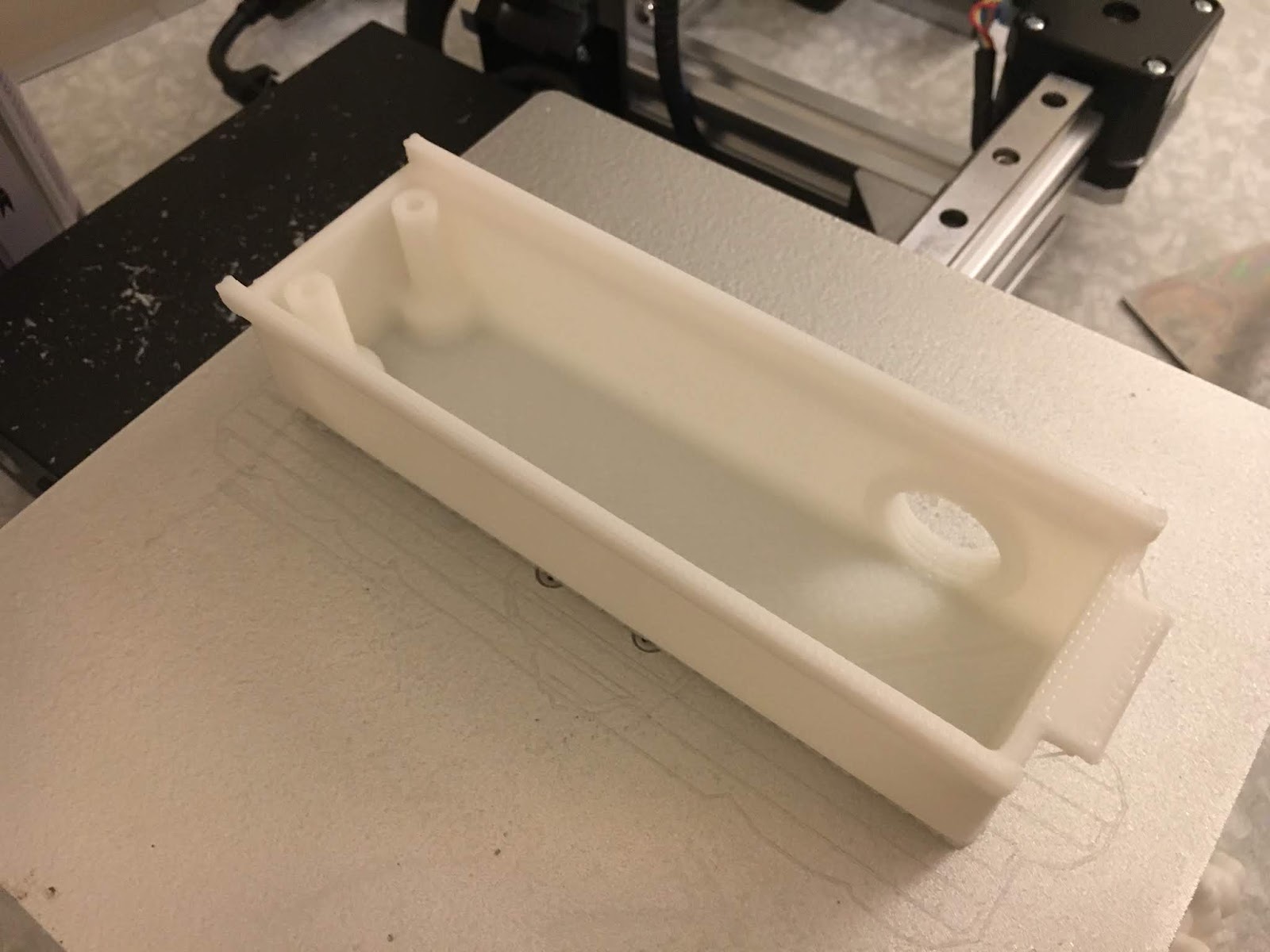
It took 9.5 hours to complete ie it ran over night. In the morning we had this:


Here we go. Got the spatula under one corner and off we went. This time it contained recognisable / usable features....


The "raft" peels off easily enough and although I don't know how they do it, the remaining surface is pretty good. I wonder how they manage to lay the part on top of the raft without it fusing? Must be something to do with the speed eg they manage to get it laid down and chilled off before it can fuse with the raft.


The various supports came away easily. And the acid test - as you can see, the cable gland screwed right in once I'd cleaned out the remains of the supports:


Job's a good 'un.

Friday 2 November 2018

Proper wiring for the DMM servos - and 3D printed plastic cover for connections

The wiring that comes on the DMM motors is some way from being suitable for use on a machine tool. I'd already resolved to make a cover for the motors to keep coolant and swarf away from them, as they aren't remotely sealed. The encoder cable is also a bit of a joke, being supplied with a Dsub 9 way connector. They also supplied a male to female extension for the encoder but this is simply an IT-grade RS-232 cable. Apart from the fact that these connectors can't be sealed in their supplied form, they are big and ungainly. 

The obvious solution is to chop them off and start again. Unhelpfully, the encoder cable terminates to a PCB which is submerged in some form of potting compound. 

On the upside, I have some pukka oil resistant drag cable and it would be rude not to make use of it for its intended application. I got this from Andy Pugh some time back for this actual purpose, although it's taken me a while to get round to it.....

This stuff is labelled "3 x (2 x 0,14D) + 4 x 0,14 + 2 x 0,5 QMM", then there's a load of stuff about ratings, such as the UL file number (E170315), AWM cable style (2448) etc - but no manufacturer's name. So what, the first part tells us all we need to know. 

Here's the motor with its external end cap removed. The encoder is under the inner plastic cap. Not much point looking much closer - I did this before and it's all potted. Not much to see.


Here's a pic from before:


Similarly, here's the stator connections:


I previously reterminated the stator cable: 


Ah well, let's get on with it.

The 2 tiny drives have separate stator and encoder cables. I already wired them in to the cabinet before I started to question the suitability of the std Dsub connectors for this application (swarf, coolant etc)


1 cable and 1 Dsub connector per motor: 


Where should I cut the wiring?


For the record, here are the existing rotor connections. Yellow is ground.


At the controller end of the encoder cable is this module, built in to a Dsub housing. Nothing special - it's a dual bidirectional line driver. Industry standard SN65C1168.


Did some reverse engineering:


There's a little space around the motor. I'm going to make a cover that will protect the cable inlet and also provide room for some retermination. The green drag cable will come in the side via a cable gland, then the rotor and encoder lines will go in the back as before.


A bit of messing about in Fusion and we have this:


I tried rendering it but this MSI all-in-one i3 machine couldn't pull the skin off a rice pudding and I lost the will to wait for it to complete:


I'll print this on the Cetus 3D during the week and see if I made any significant cockups.

Meanwhile I will attempt to rewire the motor and encoder onto the drag cable. Don't need to wait for the cover before starting that...

Final assembly and test of the spindle nose adaptor - RESULT!!

After the recent distraction caused by the 3D scanner, resurrecting the 3D printer and buggering about with the throttle bodies for my Honda...