Who are these people and what is this thing?
Arc Captain have been actively promoting and marketing their range of welders in the US and EU over the past year or more. They seem to be well received, with few reports of failures or poor service. They also appear to be well built and are offered (in the US and EU) with a 5 year warranty.
The "TIG200PACDC" is actually a fairly good description - a 200A AC/DC TIG welder with pulse. And if you look at their AliExpress shop front, it's on sale at £375 delivered, although you can't actually order it from the UK.
There are some helpful videos on Youtube that include some shots of the internal construction, which actually looks pretty good, speaking as an experienced power electronics product developer. Famous last words?
While these are available through local channels in the US and EU, here in the UK we can't buy them, either directly or via Arc Captain's Ali Express shop. That's almost certainly due to the monumental act of stupidity that is known as Brexit. Anything that has to come into the UK now needs to have the pointless "UKCA" mark instead of (as well as) the previously established CE marking. Furthermore, we now have to pay taxes on anything that arrives via the EU. A wonderful legacy from the wankers who conned the gullible masses into voting for it.
These Arc Captain products are aimed at serious hobbyists and semi professionals rather than full time professional welders. Similar products available in the UK might include brands like R-Tech and Jasic but these come in at £1500-1800. There are quite a few Chinese brands in the same space but they tend to have very limited exposure here, so we have little to go on in terms of feedback and reviews.
Can I import one myself?
In order to be able to purchase one of these things from AliExpress, you need an EU shipping address. One way to do that is by using a "freight forwarding" service. There appear to be a few of these that non-professionals like us can use for one-off purchases. After a bit of sniffing about, I found Forward2me, who have depots in Germany, Turkey, Japan, USA and UK.
Here's the process:
- Register / open an account with Forward2me
- Create another address in your AliExpress account using one of the addresses they supply - in my case I used their German address which is in Brandenburg next to the Polish border.
- Purchase your goods from AliExpress using that German address and download the invoice.
- Upload the invoice to your Forward2me account. They now know to expect a delivery and how to tie it to your account when it arrives.
- Await the notification email from Forward2me telling you the delivery has been made (you can track the package from Chine to them via AliExpress).
- Select the delivery service and destination address in the UK. You have to pay at this point, based on its size and weight!
- Watch the progress of the delivery as it makes its way across the border to Poland and thence to the UK.
- Pay through the nose for another set of taxes and admin charges - I don't see any way to recover the EU VAT.
- Finally, take delivery!
And the cost?
- £441.81 purchase cost from AliExpress, including taxes and carriage to German address.
- £97.52 Brexit tax and UPS admin .
- £44.16 Forward2me payment for the UPS shipment.
That's a total of £583.49 delivered to a UK address.
How does that compare?
Both come with 5 year warranty. In my case, if it were to fail, I'd need to return it to Arc Captain in China.
Rightly or wrongly, I've gone for it. At between 35% and 40% of the other candidates, it seems like a gamble worth taking. Time will tell....
Interesting. I contacted Arccaptain directly to ask if they planned to market their products in the UK. Although they told me the had no plans to do so, the product and its packaging shows the stupid Brexity UKCA marking and there is also a UK address listed on the packaging. Perhaps they planned to do so, then changed their minds for now. Or the person who replied was talking out of their arse.
Anyway, let's see what we have got here. Ooof - things are a bit out of shape here, literally:
Here's that stupid UKCA marking:
Another sign of damage:
One of the clips that holds the front moulding to the housing is still attached....
...and the corresponding feature on the moulding is slightly damaged. It's recoverable though.
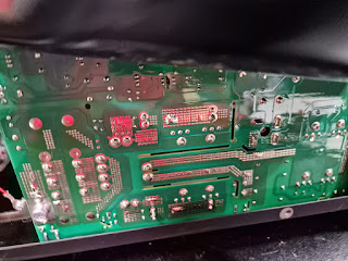
Here's the interesting bit, speaking as a power electronics product development engineer. Looks like 600V IGBTs from here. Some sort of Chinese brand I've not heard of.
The incoming mains is rectified and fed into some bulk caps via a soft start relay. There appears to be a full bridge driving the transformer (4 of those IGBTs)....
....then a full bridge on the secondary, implemented using 16 TO-220 devices. I assume these are MOSFETs. The part number isn't visible in the photo but I don't think there's much doubt.
Rufus is actually quite impressed. This is him singing his MOSFET song:
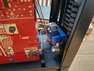
There appears to be a Hall effect current sensor on the output.
Those MOSFETS have "15N075" in the part number. Presumably 150V devices.
Here's the main controller MCU. Can't read the part number under the conformal coating.
Looking at the packaging, you can see how the damage to the housing is aligned with these marks. Some clot at either DPD or UPS obviously threw something at it.
From the inside:
This slotted vent has suffered but I can't be arsed to bend it back yet. Perhaps I could do so with some smooth jawed pliers later.
The housing doesn't lie fully completely flush but it's pretty close.
And same goes for this slight ding at the rear:
Here's the serial number etc:
But at least it works!
Here's the starter kit for the torch:
Passable looking 17 sized torch with both a switch and a pot. The cables have large DINSE connectors for quick attachment.
One thing the torch kit is missing is a tungsten electrode. Never mind - I have a selection already. One thing I'm not certain about is which ones are thoriated and which are zirconiated, ceriated or lanthanated. Thorium is radioactive, so given the choice I'd rather not be using them. Lanthiated (gold) electrodes appear to be just as good for both AC and DC use, to the point where some suppliers only supply them.
White is zirconiated and show no radioactivity:
Here's the background rate - typically 12-17 counts per second:
Red is thoriated. We are all going to die.
Gold is lanthanated.
Green is pure tungsten:
Although I have some gold electrodes, my selection is limited. Amazon to the rescue - 1.6mm, 2.4mm and 3.2mm are on their way.
Finally, I want some reasonably robust hose for the argon supply, to replace the transparent PVC crap they supplied. This requires a 3/8" BSP (right hand thread) hose nipple for the regulator end. The local welding supplier had blue hose with those already fitted, but refused to sell me them, as blue is reserved for oxygen and my use would not be compliant with standard practice. Never mind, I have a couple of nipples already, so can make up my own hose when the 5m length of black polyurethane hose turns up later today.
Next: connect up the gas and try the fucker.


