Retrofitting 1983 Shizuoka AN-SB CNC milling machine, Bridgeport mill, Colchester Bantam lathe and 1982 Tree UP-1000 CNC lathe with modern controls - and other workshop stuff
The cross slide (X axis) servo motor has a 14mm dia shaft and I have a 16t toothed pulley. This mates with the 32t pulley on the cross slide ballscrew. However, it's only about 15mm outer diameter. So clearly I will need to make up a stepped adaptor. This will fit on the servo motor shaft, engaging with the 5mm key and locking in place with an M6 grub screw.
Machining the pulley:
The belt guides on this pulley are superfluous. The larger pulley has them, so they can come off this one for starters. They are only staked lightly in place, so doesn't take much to pull them off.
16t pulley fits the 4-jaw nicely. Dial it in carefully, using the machined boss...
And drill it out with a nice, sharp 7.5mm HSSCo drill.
And face it off
Looks good
Machining the spindle adaptor:
A piece of mystery steel from the window ledge. Skim it off so that it's concentric. Difficult to get a good finish with a carbide tool when you are manually feeding it.
Bore it out 14mm with carbide boring bar and CCGT06 polished insert.
Bottom line is - does it fit? Yep, nice sliding fit.
Turn it round and pick up on the outer diameter I've just skimmed so it's set up concentric with the internal bore.
Nice blue chips - you don't get chip breaking unless you get enough heat into the swarf. And the ribbons you can get with girly surface speeds can be lethal.
Spot on diameter, now chamfer the edges
Loctite clone adhesive to bond the pulley to the shaft, although it was a fairly tight push fit anyway. That's not going anywhere.
Keyway:
The key stands out 2mm from the shaft
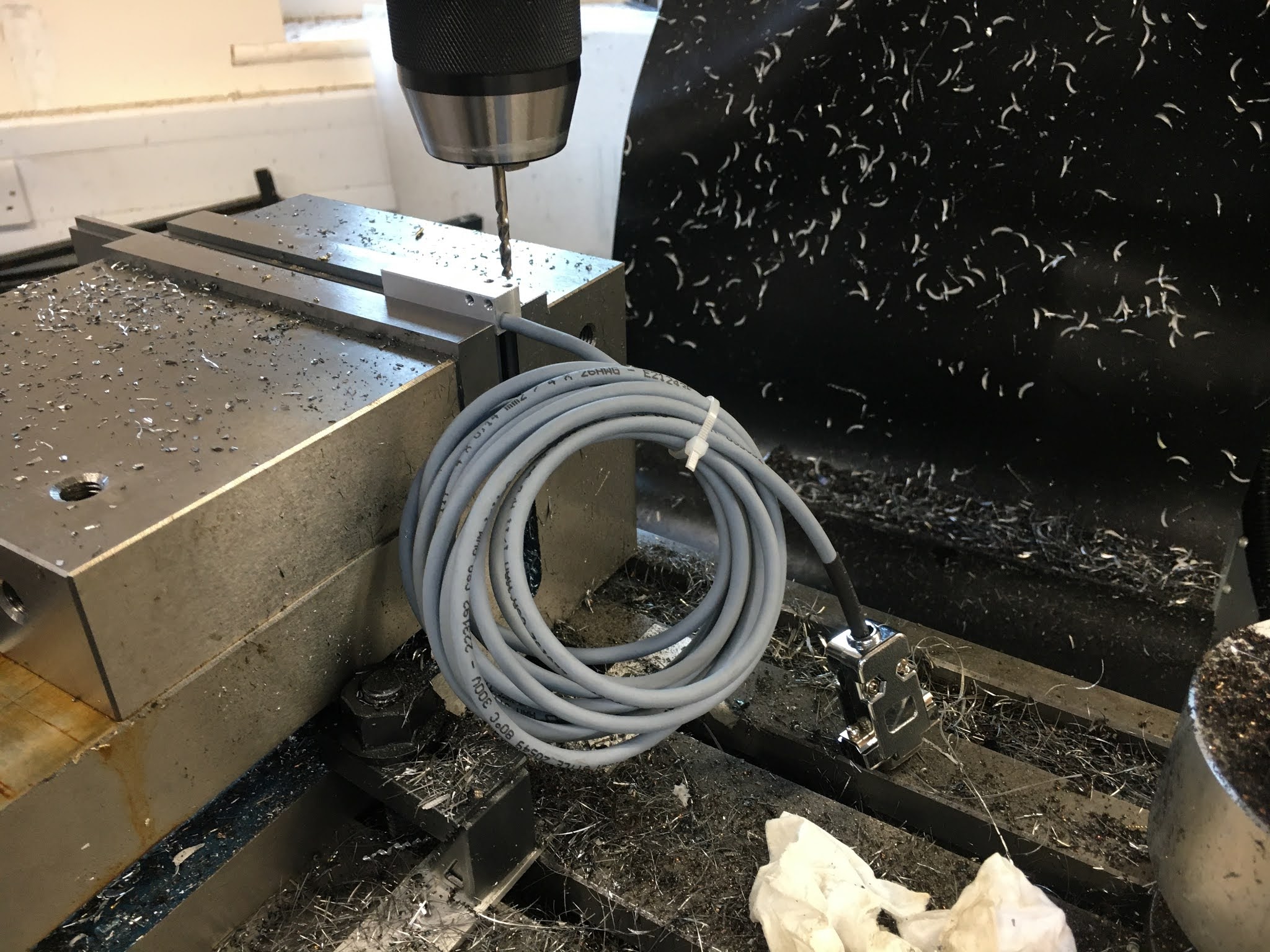
Now to machine the keyway in the adaptor. None of this messing about with slotting - I'll mill a radial slot instead.
Mount the adaptor vertically with a vee block
Pick up the bore centre and the top surface with the Renishaw probe
4mm carbide end mill, 0.5mm either side of centre (in X) to a radius of 9mm from the centre line (in Y) and a depth of 16mm ie 4xd (in Z). Trial fit looks good:
Drill 5mm for M6 tap.
M6 grub screw. Job done! I knew it would be a fiddly business but it allows me to drive the cross slide ballscrew with a 2:1 reduction.
Various electrical bits remain to be fitted under the cross slide.
The encoder read head, magnetic strip and encoder cable fit one one side of the cavity (double red dots).
On the other side is the +limit / home switch and -limit switch (single red dots).
Not very dramatic action here but it needs to be done, so let's get it out of the way.
Cross slide encoder:
Let's get the linear encoder fitted. Here's the Machine-DRO datasheet for the mini encoder. Not impressed that they can't even get the drawing right. My encoder head has mounting holes in the wrong place - "wrong" if you consider the datasheet to be "right".
Even a blind fool can see that the datasheet doesn't reflect the reality of what they are supplying.
Luckily I noticed this before I created the CAD model, so the tapped holes in the saddle body are in the right places. But now I need to drill out the fixing holes so they are M3 clear rather than M3 tapped.
3.5mm drill, placed with the touch probe and DRO:
Countersunk and fitted with M3 CSK screws. Nice - has the required clearance for the magnetic strip. I'll leave that for now though, so I don't fuck it up.
Limit switches:
Simple enough job. But I'm not used to these tiny girly screws. Those holes are tapped M2 x 0.4, requiring a 1.6mm drill and this tiny tap wrench.
Hopefully that's most of the machining done for now. Let's try it out:
Once I'd deburred the edges, I've got a perfect sliding fit in the slot. It needs to be sliding so I can slide the cross slide body into place with the ballscrew / ballnut / yoke assembly in place. Well that's a reasonable start.
This lot fits pretty nicely, although the coupling is very slightly oversize. I'll need to shave that down at some point.
My balls have dropped finally:
However, after playing with the movement for a while, I found something was interfering with the coupling, getting caught between the coupling and the saddle. Turned out to be some of the bearings from the ballnut. WTF??
Obviously these can't escape once the ballscrew has been inserted, so clearly this must have happened during the insertion process itself. The displaced balls were held behind the plastic seal, which finally gave way and released its captives as I played. Bugger.
I've always suspected I'd have enjoy the pleasure / challenge of repacking a ballnut before too long. And today was the day it seemed. The wait is over.
Each of the end seals was held in with a couple of tiny pointed grub screws. Luckily I have a set of tiny hex keys. Although this isn't the smallest one, it's getting close to an inhalation hazard.
99% certain I recovered all the balls, as most were caught in the saddle cavity, with a few in the chip tray directly underneath. Lucky I cleaned the tray recently before starting on this. Now I need to get the buggers back in....
It's very similar in construction to the Chinesium ballnuts I used on the Bridgeport conversion.
There are quite a few Pootube vids showing how to do it. This one isn't the best quality but actually shows how to do it if you don't have a bucket of new balls to hand:
Looks simple enough. What could possibly go wrong? Well plenty of things come to mind....
Not easy to see but there's a circlip in there (not sure what for) and beyond that there's a plastic diverter. The balls need to be fed in just after / below that. And in order for that to be possible, the screw needs to be unscrewed far enough to expose that section of the ballnut body. Then a pair of pointy tweezers is all you need to push them into place. Actually quite straightforward. Phew.
Finally, replace the seal. Some seals have a groove around the circumference. These have a couple of holes, so the seal needs to be aligned carefully with the grub screws, hence the black markers.
Next - the balls up:
I'm hoping this ground ballscrew will show relatively little axial backlash - at least when compared with the Chinesium ballscrews used on the Bridgeport. Let's assemble it and see what we've got.
Bollocks - that's a 32t pulley and I have around 1 tooth's worth of lost motion before the cross slide actually moves. With a 5mm pitch ballscrew, that's 5000/32 microns or ~150um. WTF???
Using a slightly more scientific approach, I am measuring ~130um of actual axial movement of the ballscrew. Well that's a relief - it's not the legendary Japanese ground ballscrew - but what is causing it?
It's quite simple - the 6200 ball bearing itself has ~130um of axial backlash. These are genuine Nachi bearings, so it's unlikely to be a faulty part. More likely The Stupid Fat Bloke has fucked up again.
Sure enough, only a cursory look through the app notes from the likes of Nachi, Koyo and Schaeffler (INA FAG etc) tells you why. Talk about beginner's mistakes...
The deep groove (6200) ball bearings don't have magical zero internal clearances. In fact, they have the best part of (wait for it).....125um of radial clearance. This translates into something similar when seen as axial clearance. So they come with some initial backlash.
To make matters worse, Fat Boy thought he was being clever specifying "C3" tolerance bearings, thinking these would be somehow "better". In fact, they have looser tolerances to allow for operation over a wider (=higher) temperature range. The so-called "standard" clearances would have been better. Oh well...
To get anything approaching zero backlash, you need to have a pair of back-to-back angular contact bearings. They are designed to have a controlled preload when clamped together in a pair. You can get several steps of preload, depending on the application. However, for my needs, the "standard" zero clearance would most likely suffice. Time to get more stuff ordered up. This is going to require a pair of 9mm angular thrust bearings, rather than one deep groove bearing. I can't see that a double row angular contact bearing would do the trick, although you'd guess it would, otherwise what would be the point?
From Koyo, you can see that a C6 bearing would be rattling like a sausage in an alleyway. The table only extends to C5, by which point we have 30-40um radial clearance. Not sure exactly how that translates to axial but either way it's not good.
So I've ordered up a pair of Nachi 7200 bearings which will arrive while I get on with other stuff. They will take up more axial length than I'd planned but at a push I can simply fit 2 of them by using longer fixings for the bearing retainer plate.
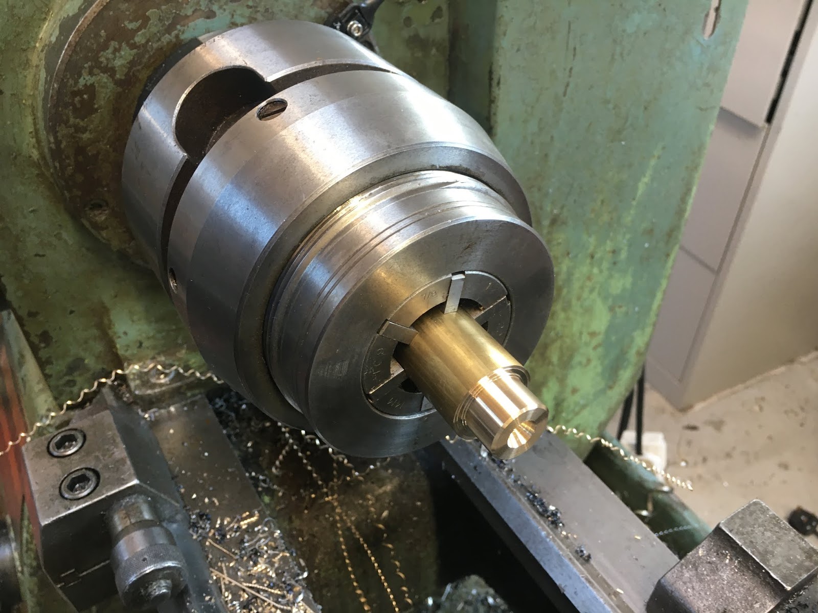
So firstly, chop off the excess length and face off / turn down.
Both ends done - coupling at one end, bearing and pulley at the other
Now make up a locknut with M10 x 1.0 thread. I have some nice 1" bronze, so why not use it? Nice to machine and very colourful!
The tap is clearly nice and sharp....
Nearly done. I need to drill a couple of holes in the nut so I can use circlip pliers to tighten it. I'll do that in the mill later when it's next in use.
So that's the ballscrew pretty much ready to slot in. I'm thinking that I will drive the ballscrew via the coupling with a piece of 8mm rod initially, to avoid having to butcher the original leadscrew until it's absolutely necessary - or even at all. Something to think about....
Machining the underside of the cross slide body:
Let's prepare for machining the underside of the cross slide now. I'm almost at the point of replacing the leadscrew with the ballnut but first I have a few mm to remove from the underside of the cross slide, to make room for the ballnut yoke, the encoder read head and the limit switches. Also, I need to machine the fixing holes for the ballnut yoke (M5 clear, with plenty of rattle). Although it would still be possible to use the original leadscrew and nut at that point, I'd need to pack the nut out to do so.
Let's double check the dimensions, particularly the required height of the underside relative to the ballscrew centreline. If I got this wrong, the ballnut won't be at the correct height for the ballscrew and I'd have to bugger about with packing or machine some more off the yoke, depending which way I erred.
Design height:
In Fusion, I see the centre height of the ballscrew above the slide surface of 6.36mm.
Measuring with my cheapie digital calipers, I see 6.45mm, with >20-30um tolerance. Given that I have designed the rear bracket to have the best part of 1mm adjustment at the fixings, that looks pretty safe.
Now I need top check the ballnut yoke height vs the dovetails in the cross slide body.
Ooops-ette. The yoke is 19.2mm, not 19.06mm. It's currently 0.14mm too tall. Looks OK, although not 100% as planned - presumably due to manual measurements way back when. I can easily accommodate that in the bracket adjustment.
The channel is 25.4mm (1") wide and the ballnut yoke is 28.5mm wide, so I need to machine a shoulder on each side, of 1.55mm width with enough depth to clear the adjacent lands ie ~1.5mm. That's a pretty trivial mod and means I can refit the original leadscrew nut at a later date without messing about - there's no point of no return.
So:
Machine shoulders at either side of the yoke: >1.5mm depth, leaving 25.4mm width.
Machine the underside of the cross slide body.
Drill and counterbore the yoke fixing holes. These are now M5 fixings - originally showed M4 which are a bit spindly, yet there's room for larger jobbies.
Sacrilege time:
This is a lot less significant as surgery goes, compared to the butchery I perpetrated on the saddle.
Pleasingly, Tim Paterson's post processor add-in worked splendidly and although there was no tool change, it handled the replacement of the rapid feeds nicely.
Slight problem-ette, though. Half way through the operation (one side done), the machine stopped and refused to resume, claiming an e-stop situation. Bugger. At least it simply came to a halt with no harm done.
In fact, with the table in the middle of its envelope and the actual e-stop clearly not depressed, there wasn't a "real" e-stop at all. But on this machine the limit switches are on the same input as the e-stop, so more likely was that they were the root cause. Annoyingly, I'd forgotten to tell the tool library that the BAP300 tool would be cutting dry, so the coolant came on and the tap wouldn't completely stop the flow. The Y axis limit / home switch assembly is in this little box under the saddle and sure enough, when I loosened the screws on the cover, it was clearly full of coolant.
It's obviously getting in through the top. I'd seen previously that it was full of neat oil but couldn't tell if that was coolant or lubricant, not least because the previous owner had only ever used neat oil.
Anyway, dried it out and machined a slot in the cover to enable the egress of any further further ingress.
And back into action. Finally for the cross slide, I needed to counterbore the yoke fixings:
Job done for the cross slide body. Now let's see how it goes together....