Retrofitting 1983 Shizuoka AN-SB CNC milling machine, Bridgeport mill, Colchester Bantam lathe and 1982 Tree UP-1000 CNC lathe with modern controls - and other workshop stuff
There's absolutely no reason to create the whole Bantam in Fusion 360. I can design and develop the critical parts without needing the whole thing to be modelled. But that's no reason not to.
Apart from anything else, it's a great opportunity to prevaricate and put off doing any actual physical construction.
So with that aside, here's what I have at the moment. I've recently added:
Beefed up spindle motor (3.0/3.6kW WEG TEFC induction machine).
Cover for the power feed / screwcutting gear train.
Main swarf shield
Headstock swarf shield
Drip tray
Feet for the bed casting
Drag chain (R48, as mentioned in last post)
This gives a more complete view of the entire machine.
Here's what a Fusion 360 render looks like from the front:
"Turn round, love"
Still to come perhaps:
I have no cabinet pedestal feet yet - this may come soon
Tailstock
Control cabinet
Cosmetics such as the gear select levers, power feed gearbox
Apron and main leadscrew
These are even more unnecessary than what I have done so far but I get a feeling in my bones that they will happen soon enough.
Not been doing a great deal in the workshop recently, partly due to grief / stress at work and partly due to uncertainty over the Bantam cabinet build. I've got most of the key parts now, give or take, but before I start drilling and cutting stuff, I need to convince myself I have got a sensible concept in mind. I'm getting there but haven't arrived yet.
I ordered some Igus "E14 energy chain" from RS recently. This will carry the various cables from the moving saddle assembly back to the control cabinet. Having received it and had a good play with it, it looks like a pretty sensible product in general terms and I seem to have got the dimensions about right. However, the links are open to swarf getting in, which doesn't feel right to me, given where it will be operating. The bend area is most likely to be operating close to where the machining action is happening and the "inside" surface would act as a fine trap for small bits of swarf. I can imagine them worming their way into the cables with time, resulting in intermittent shorts.
So - close but no cigar. Not certain I want to build my machine around this.
What now then, fatty?
Before getting too clever on the detailed design front, I thought I'd better see if there's a better solution out there. Sure enough, there's an (almost) totally enclosed alternative that can be bought directly from Igus UK - the "Series R48 E2 Tube".
I missed this route, as I expected that I'd need to be looking at the likes of RS, Farnell, CPC etc for ex-stock delivery in the UK. However, I got a confirmation email confirming it's stocked in the UK and (apart from the long bank holiday weekend) available for immediate dispatch. Bargain buckets.
Once you've specified the length of the chain and specified the mounting brackets (end pieces), you can download the assembly and import it into Fusion. This wasn't too tricky but when I got it imported in there, I was a bit underwhelmed:
Yes, the central portion is a single body ie incapable of articulation. It's not strictly necessary or even enormously helpful to go to the bother of modelling the chain in the Bantam assembly but I thought I'd have a go at creating my own. Bollocks - why not?
Modelling drag chain in Fusion 360:
The basic parts are available to download including the mounting brackets and the link component, from which the chain is made. So off we go. Here's the chain with a couple of links and the end brackets highlighted for no obvious reason, other than to give some visibility into the assembly:
The key to getting its behaviour right is the joints implemented between the links. The characteristic behaviour is due to the restricted movement, which seems to be 30 degrees in one direction and zero in the other. That and the connections to the end brackets provides most of the constraints. The final joint required is the sliding / offset joint between the end brackets. Once that is in place and the "fixed" nd bracket is grounded, you can grab the "moving" end bracket and everything works as it should.
The (25) links were all manually assembled, which took a while. The angle of articulation of the links is a key parameter when it comes to the minimum bend radius, which in turn is one of the key behaviours of this chain. So I used the parameter table to create a user parameter to control all of the joints used between the links. Then I was able to finesse the angle to get observed behaviour.
The calculations are fairly simple. The bend radius for a chain made of these links is claimed to be 60mm and the link length is 30.3mm (from the datasheet). So the angle of each link to the tangent is 2*arcSin(15.15/60) ie ~15 degrees. After a bit of frigging about, I ended up with 30.5 degrees max on the joint limits:
Once the revolute joints for the links and the sliding joint for the end brackets were in place, it behaved like the real thing.
My workshop PC is a pretty feeble thing, with an i3 processor and integrated graphics. However, if you don't try to move to suddenly or quickly, it just about manages to keep up:
Next, integrate with the main machine assembly in Fusion. Not just for bragging rights but actually to figure out the best place for it to live. Here it is with the saddle in its closest position to the headstock:
And at the other extreme:
I can clearly move the fixed mount slightly nearer the tailstock end by 50-60mm or so, FWIW.
In terms of the end view (ie X & Y position), this looks pretty reasonable when you eyeball the machine itself. Wrong drag chain but it shows the general idea:
Looks workable. The E48 cable won't arrive until Wednesday at the earliest and I will be busy with work during the week anyway. So back to the cabinet for now.
Right, I've got the system running on the bench and cut my first part. Next step is to get into the cabinet build. I've got myself another IP67 steel cabinet from CPC (Europa brand) and some of the bits and bobs I know I'll need.
Workshop reorg:
First, let's clear the decks by moving the lathe to the end of the main work bench. This will give me more space on the bench and will allow me to wire up the cabinet on the bench while also connected to the machine itself.
PC Build:
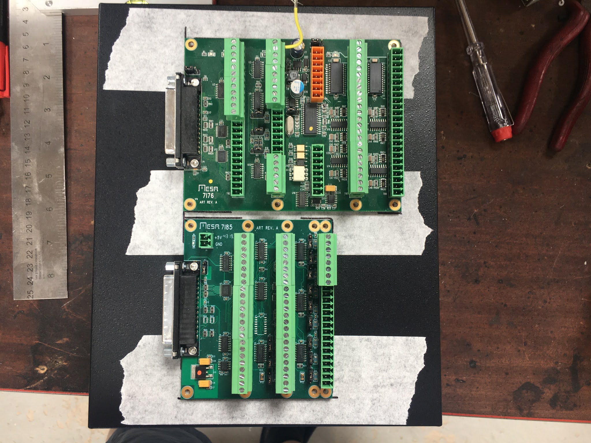
What about this PC then? There's the slight matter of wiring up the two Mesa boards (7i85 and 7i76) to the 5i25 in the PC itself. Problem is that the cabinet isn't enormous. I've chosen it to fit on the end of the lathe and of course when you get down to it, you tend to find there's never enough space inside to allow you to fit all the stuff in and wire it up sensibly.
Here's the PC and the external boards.
And the cabinet baseplate with the VFD and servo drives plonked down to get an idea of how little space there is. I need to think carefully here, to avoid the old quart vs pint pot scenario.:
So my cunning plan is to mount the boards on top of the PC. A bit like this but with the case on, obvs. But this illustrates how the cables might run, given the positions of the various boards:
For my own records, here are the existing connections (mainly encoders, limit switches, servo and VFD controls):
7i76 (step/dir, GPIO and spindle). I'll remove the 7i76 from its plastic tray:
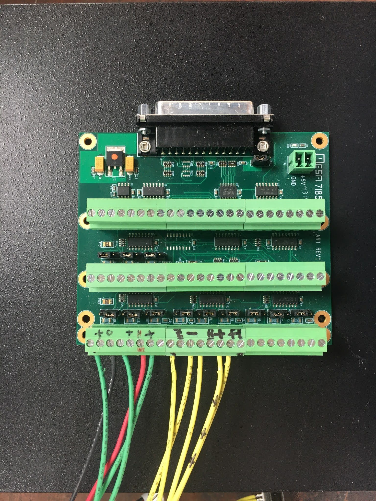
7i85 encoder board:
This would work:
Mark out holes:
A bit of buggerage with a load of M3 screws and Bob's your uncle. The 7i76 is wired up using the ribbon cable and a gender changer thing (that yellow bit). I now need to make up a cable for the 7i85. The main 5i25 D connector is hidden just above the main motherboard port:
I'll cut the 2m long D25 cable and reterminate it about here:
But the shitty Chinesium D25 cable I got from ebay (Amazon?) is visibly crap. Doesn't even have any shielding. So I'll use the other cable. Forget where I got that one (possibly came with the 5i25/7i76 combo?) but it looks like a better class of cable. So now I've chopped both of them up - hope I won't need either of them again....
Strip and tin all the wires. There are clearly more than 25 of them, so some obvs aren't used.
Prepare to solder them. This won't be a whole bundle of fun.
God, that was a fiddle:
For identifying the correct wires and checking them afterwards, I used a DVM in beep mode. This did the trick, so it's time to make it secure now.
The screen strands were completely unsolderable, despite applying loads of heat and flux. Ended up giving up on the soldering attempt and fitting a crimp and soldering to that instead. God nose what special plating they had used on the wire.
Looks as if I almost made that too short! It's not quite as bad as it looks....
Download / extract the bitfile to folder /lib/firmware/hm2/5i25/configs/hostmot2/ then go to that folder in a terminal session and run mesaflash like this:
muzzer@LinuxCNC:/lib/firmware/hm2/5i25/configs/hostmot2$ sudo mesaflash --device 5i25 --write 5i25_7i85_7i76d.bit Checking file... OK File type: BIT file Boot sector OK EEPROM sectors to write: 6, max sectors in area: 16 Erasing EEPROM sectors starting from 0x100000... |EEEEEE Programming EEPROM sectors starting from 0x100000... |WWWWWWWWWWWWWWWWWWWWWWWWWWWWWWWWWWWWWWWWWW Board configuration updated successfully. Checking file... OK File type: BIT file Boot sector OK Verifying EEPROM sectors starting from 0x100000... |VVVVVVVVVVVVVVVVVVVVVVVVVVVVVVVVVVVVVVVVVV Board configuration verified successfully.
You must power cycle the hardware or use the --reload command to load a new firmware. muzzer@LinuxCNC:/lib/firmware/hm2/5i25/configs/hostmot2$
Now that I have them disconnected again, let's have a closer look. Apart from a couple of screws, the casing simply snaps in place. Equally, it unsnaps easily enough. So it might be rude not to take a closer look.
Off we go:
Here's what it looks like from the outside:
Pretty much the standard appearance you'd expect from a servo drive. On the left from the top - separate AC inputs to power and control circuits, braking resistor connection (loop through to use the built-in one) and (at the bottom) the motor phase connections. On the right from the top - RS422/485 connection(s) via RJ45 connectors, then the signals IO and finally the motor encoder.
At the back, a built-in braking resistor and the cooling air tunnel (fan at bottom, exit at top)
Here's the fan cover. I replaced the "Angry Bee" brand Chinesium fan that came with them for better quality (quieter) PAPST numbers.
Let's dive in:
The front cover unclips, revealing 2 PCBAs. One is the high voltage power board and the other is the IO / digital controller board.
This is the IO and digital controller board. That's a Lattice FPGA under its conformal coating. On the other side is a similar QFP package which is almost certainly a 32 bit microcontroller. Couldn't be arsed to remove the board to look more closely and find out what sort it is.
Here's the bottom of the power board. The IGBTs are all housed in a flat package. Pretty sure it also includes the braking resistor IGBT. The input rectumfrier is a 3 phase jobby obvs but it's a std looking square package with a sneaky, extra (5th) pin.
I didn't take it any further apart.
And there you have it. I like to take stuff apart, to see what I am dealing with.
Conclusion: Doesn't look too bad. It's certainly not up there with the Yaskawa Sigma drives but it's way ahead of the DMM Tech servo drives I have on my Bridgeport conversion. Although the software is pretty basic and the fans require ear protection, the physical implementation isn't as bad as I'd feared.
Steady on! My lathe conversion is now 99% functional, albeit laid out on the bench for now. The next step will be to rip it apart and install it for real in the cabinet I've just bought. Before doing so, I'd like to convince myself I have a functional system by machining a test piece. This would be a major milestone to tick off at least. I see that the lathe_pawn.ngc example file that comes with LinuxCNC installations is missing a lot of info you'd actually need to run a real machine. I guess this is enough for running a sim but I'll have to create a proper version myself. For instance, there are no tool numbers or offsets specified and it is missing some of the initialisation lines you'd want to see at the start and end of the file.
Then set the RH version up in the Fusion tool library:
CAM setup:
The stock and machine setup could be fraught with opportunities to crash the tool / work / chuck etc. There's a bit of an insight into how this works in the latest (Dec 2019) lathe update from Autodesk.
Roughing settings:
Finishing pass:
Post processing:
There's a LinuxCNC lathe post processor in the Fusion post library that seems to work. At least this code specifies the correct tool (T4 in this case). That feels like a good start.
However, when I try to run it, I get a couple of errors:
I have a couple of lines at the start specifying U and W coordinates
I get a message saying it can't find the specified tool 4 in the tool library
This would be my first ever lathe program, so perhaps the U and W coordinates are fairly normal but I can't see anything in the Peter Smidt books about them. I can delete them, which gets rid of the error message but presumably the LCNC post produces them for a good reason?
As for the tool library message, this may be another symptom of the immaturity of the PB Lathe GUI. When I edit the library, the lathe.tbl file gets updated correctly, so T4 seems to exist and can be found / edited by other parts of the GUI. Is there any obvious reason I'd get this message?
The only way I can find to frig the system is to change the program tool number to zero(!). I guess I could do this solely for the purposes of running my one-off test piece although I don't know if the part zeroing macros would work with this method.
I'll see what state the PB Lathe GUI is in when I finally have the system installed in the cabinet and working again. That should buy me some time, otherwise I may have look into one of the other lathe GUIs. I'd certainly like to be able to use Andy Pugh's macros and obviously the tool library is a bit of an essential function that needs to be in place.
Bollocks. Let's get 'er done, then I can move on with the cabinet installation.
Just do it, fatty!
Homing the machine, then positioning the tool at where I imagine the part origin to be and zeroing the WCS should do the trick, you'd think. Sure enough it seems to get us most of the way there. A bit of air cutting with a bit of wire to mimic the tool nose suggested it was reasonably sensible, so off we went:
For some reason, it seemed that the program stopped between the roughing section and the finishing pass.
So I deleted out the roughing section and reran it so get the finishing pass out of it. This seemed to almost do the business, although it didn't completely finish off the vee groove feature for some reason.
Manually parting off:
So, I seem to have a pawn on my hands:
That wasn't a complete disaster, although I could make some comments:
The surface finish isn't exactly spectacular. I can't see any "smoothing" settings in Fusion. Perhaps there is something in LinuxCNC. Or perhaps it doesn't exist in lathe in quite the same way it does in milling? Something to look at.
The part is 0.5mm undersize on diameter. I guess this happened when I eyed up the tool nose, not being bothered to figure out exactly where to position it.
The first (facing off) move seemed a bit aggressive and resulted in "some degree of chatter". Once past this, everything else was OK.
The 0.1mm stock to leave may have been a bit light. Not sure if this is partly why the finishing pass didn't always remove any stock.
That'll do for now. So now let's focus on the cabinet installation....