Oh no. Not another accident involving a mouse? Yep. But this time it's a non-functional TIG welder, spotted on a machine tool trader group on Facebook.
An AC/DC TIG welder like this is usually about £1k new (plus vat). You might get a hooky one for half that price off the back of a Chinese lorry / back of the factory / bootleg copy if you want to take your chances but even if I did, the Domestic Manager would crucify me if she ever found out.
This one cost me £100 plus carriage from Colchester to Lancashire. Despite weighing 19kg, that bit only cost me £7. I used parcel2go to compare the options and found that Parcel Farce 24h service was the cheapest. Bizarrely, Herpes consider this to be in the "Light and Large" category, thus warranting a £25 (+vat) charge. Well they can go whistle.
Sure enough, it turned up this lunchtime. Lots of cardboard. Hope the delivery guy didn't throw it out of the van.
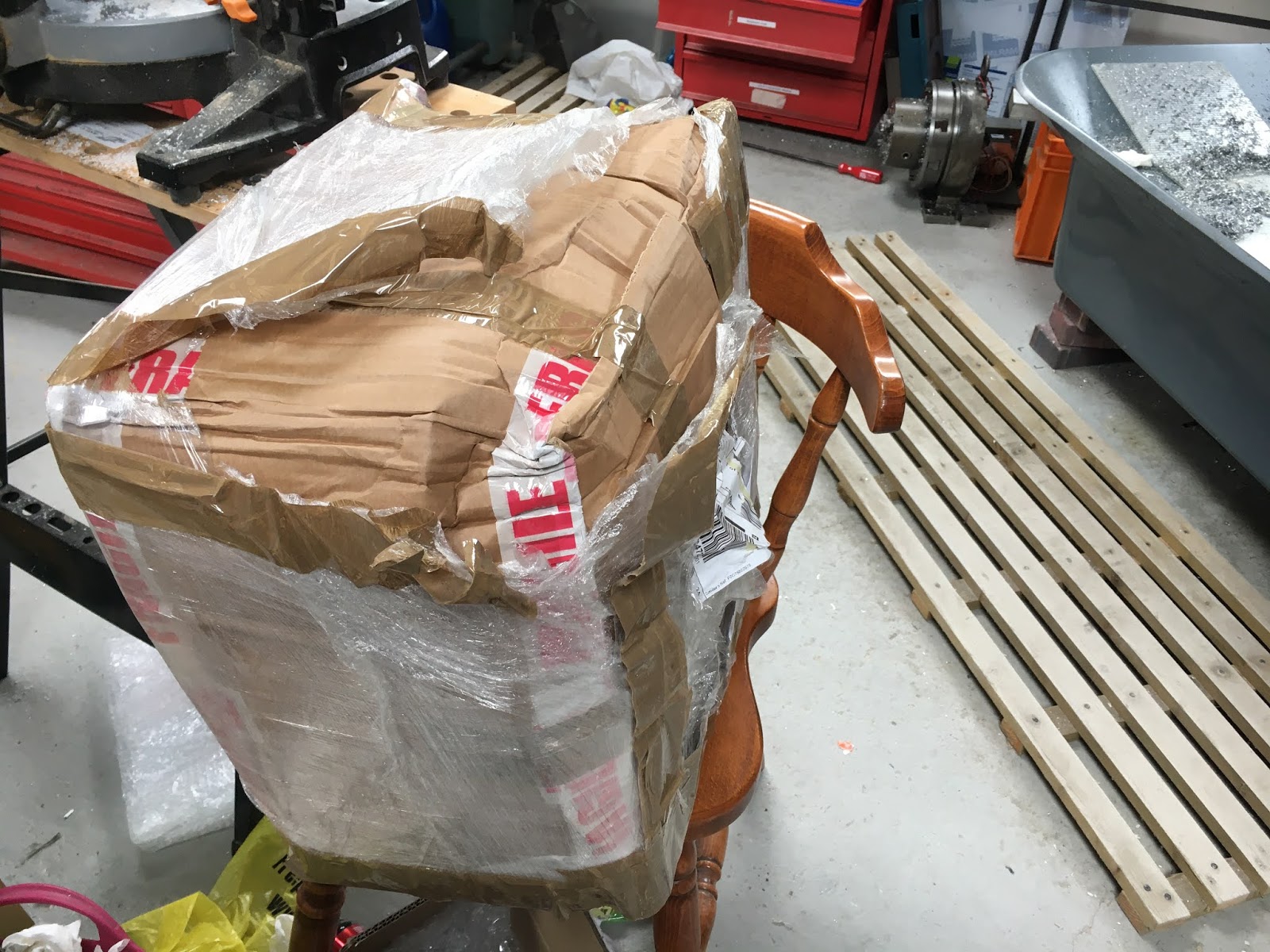

Aha. There it is.


Some ape has been in there previously.

The side covers slide out the bottom once you have removed the screws.

Thermal Arc was acquired by ESAB recently. One of the things they wasted no time over was erasing any previous technical data, service manuals, parts lists etc. In fact, you'd hardly know they'd even existed. The centre in Chorley where they possibly designed these things seems to have been closed down, so there's no possibility of ringing up and getting a copy of the manuals. Ringing ESAB technical dept resulted in a phone number. Ringing that led to a recorded message from a lady, giving the following numbers. Naturally both of those went to voicemail. So that trail petered out quickly enough.

I didn't bother turning it on, as I know it's DOA and there's no point charging up all the caps if I'm going to be digging around inside it. So let's do just that...
This is clearly the output stage / secondary board:
- Date code Feb 2006.
- An array of ISOTOP power devices. These are a mixture of diodes and IGBTs. They rectify the transformer output and switch the output to provide the AC or DC voltage. The copper thing works as a busbar but also as a current shunt for measuring the output current.
- There are 2 optoisolators at the top. These drive the IGBTs on the output side.
- 3 transformers provide isolated supplies for the controls - and gate driver circuits presumably.
- Various connectors for the torch control, chiller control, gas solenoid, display, HF circuit and power supplies.
- The big fuck off copper tabs lead to a pair of heavy windings in the output choke.
- The feed from the primary board connects up to the underside of this secondary board, so you can't see it here.
- No obvious damage or signs of magic smoke.

I need to note the connections, as I'll be taking this plate off to get to the ISOTOP devices. Note the red and black current sense wires. The big lug is the -ve output connection to the torch.

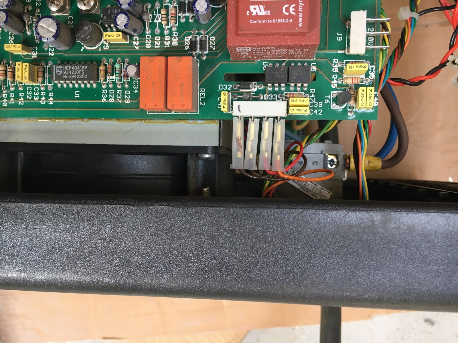
Here's the primary board.
- The rectified AC comes in from the input board as the heavy-ish red and black wires.
- There's an IMS board underneath this PCB, visible through the holes. It's a half bridge circuit, so presumably some discrete IGBTs and diodes.
- The main power transformer is visible at the bottom of the photo. The primary winding comes onto the board as 2 heavy-ish black wires.
- There's a current transformer that monitors the transformer primary current.
- The secondary is centre-tapped and connects to the -ve (torch) output via the HF transformer. This injects a high frequency, high voltage signal onto the torch to enable arc striking. The HF transformer is at the bottom left, with the primary side wires in a yellow sleeve.
- Control is done by an SG3525A (PWM controller with complementary outputs) on the piggy backed daughterboard. Fairly low tech stuff, as you'd hope.

The plate's out of the way so I can see the ISOTOP screws. Checking with the DVM, one of the IGBTs seems to be short circuit. Let's remove the board to have a closer look.

I need to note these screw positions for later. It should be fairly obvious. Yes, it should be. So I'll take a photo then.

Noting the myriad connectors which will all have to be disconnected to get the board out:


Nearly there

Finally.

Nothing particularly obvious

Some slight darkening but no real overheating when you look closely

This is the culprit.
GA200SA60S ie 600V 100A IGBT from International Rectumfriers. Short between collector and emitter and also between gate and emitter. Nothing else damaged - the current transformer must have done its job.

The gate drive circuit is pretty simple. HCPL-3031 optoisolated gate driver IC with just a 22R resistor to each of the 2 IGBTs. Both resistors appear to be intact and both gate driver optos measure identically which suggests the damage is limited to the IGBT. Looks as if I should be able to simply replace the IGBT and be on my way.
Fortunately, Farnell stock an equivalent ST part, so I can get a couple delivered next day. I guess that will be Friday, given how late in the day it is now. But that's better than "20-40 days" via AliExpress.
Apart from cleaning it up, I can't do much more than just sit back and wait...


