Friday 11 January 2019

X and Y axes up and running!

Now that the servos are wired up and running, time for a tidy up:


Everything is assembled and wired up on the X and Y axes.


Meanwhile, The Shiz sits quietly, watching proceedings....


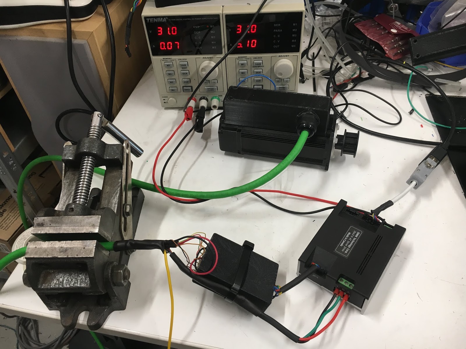
Just to prove it's actually running:


There. Next, limit switches and then the Z axis!

Wednesday 2 January 2019

Wire up DMM Tech servo with drag cable - first movement!

Well, this is it. I've got my line driver board and 3D printed housing. And now all I have to do is do a sanity check (breadboard / bench test) them before wiring them up for real with the lovely green drag cable.


Here are the connections from the encoder (at the front) and the motor (at the back). I need to splice these onto the ends of the green drag cable, then bring out the other end (CNC controller end) to the line driver board and the DMM servo driver. Fairly simple but still a slow PITA to do properly.


Fairly functional, rather than a work of art. I have a life to live, so they are soldered and then heat shrunk. After this, a cable tie to strain relieve the joints.


On with the cover and tighten up the cable gland.


Then tackle the other end, not forgetting to thread the cable gland on first!


Hold on - I need to test out the driver boards before getting too carried away. Here's the original part.


....and the bottom side thereof:


Soldered a D connector back on and a suitable connector on the other end. Photograph the original connections first!


Side by side, they need to achieve the same functionality. Original system on the left, new system on the right. D connector on one end (plugs into the motor encoder) and 6 way connector on the other, which plugs into the servo driver.


You know your cross head screwdriver is in a good shape when you can do this:


Here it is, finally connected up on the bench. Spins the motor, holds position etc etc. Also checked out the second driver board. The only issue being a crossed wire (yellow and orange) on one of the line pairs (corrected that on the wiring table spreadsheet) and I noticed that the solder blob bodge on the line driver IC was bridging the wrong pin to +5V - should be pin 4.


Good stuff - next to wire up the second servo motor, now that I know it all seems to work as intended.


Here's the final wiring table:


Here we go - 2nd motor:


Job done at motor end.... 


...and controller end. Tested OK, too:


That's that for the wire prep / bench testing. Now to wire them up to the cabinet / machine.

Final assembly and test of the spindle nose adaptor - RESULT!!

After the recent distraction caused by the 3D scanner, resurrecting the 3D printer and buggering about with the throttle bodies for my Honda...