Retrofitting 1983 Shizuoka AN-SB CNC milling machine, Bridgeport mill, Colchester Bantam lathe and 1982 Tree UP-1000 CNC lathe with modern controls - and other workshop stuff
First flip the body round and set it up again in the 4-jaw. As luck would have it, the taper nose I've just machined in the front side of the work piece is marginally longer than the step in the jaws. So when I try to mount the work piece against the faces of the jaw, the taper nose slightly fouls the next step in the jaws - and only just at that. Solution is to put some brass shim stock between the work piece and the jaws.
Sort of getting there. Something's still not quite right. I can dial it in at one position but it's cock eyed elsewhere.
Hmm. Seems that 0.25mm shim stock isn't quite enough to clear all of the jaws. I can get the radial runout where it needs to be - but with a shit load of axial runout. In other words, it's not running parallel with the spindle because it's riding on one of the jaws.
Another lot of 0.25mm shims (total 0.5mm now) just does the trick.
Seems to be about 0.1mm runout in the worst case position. I'm afraid that will have to do. I'm planning to do a final skim cut when the rest of the machining has been done, with the adaptor in position on the spindle, so i can recover some of that.
Well that was a pain in the ass. Apart from the business with the shims, the adjustors and jaws on this Vertex chuck are as stiff as fuck, so getting the final few thousandths isn't quite as simple as it was on the Burnerd chuck I've used previously. I guess you get what you pay for but something better such as a Bison was out of my range. Perhaps they will bed in with time but on this occasion, the whole carry on took me about an hour. I could do without that each time.....
I made a start on this some months ago on the Bantam but it struggled to overcome the cutting load. This was with the motor in high range ie ~1:1 ratio, yet I needed something like 500rpm. The right solution would have been to change the gear ratio, along with the corresponding settings in LinuxCNC but TBH I couldn't be arsed - and I thought I had a chuck for the Tree when I acquired that dodgy Kitagawa chuck. Now I have a better solution that will allow me to learn about the Tree.
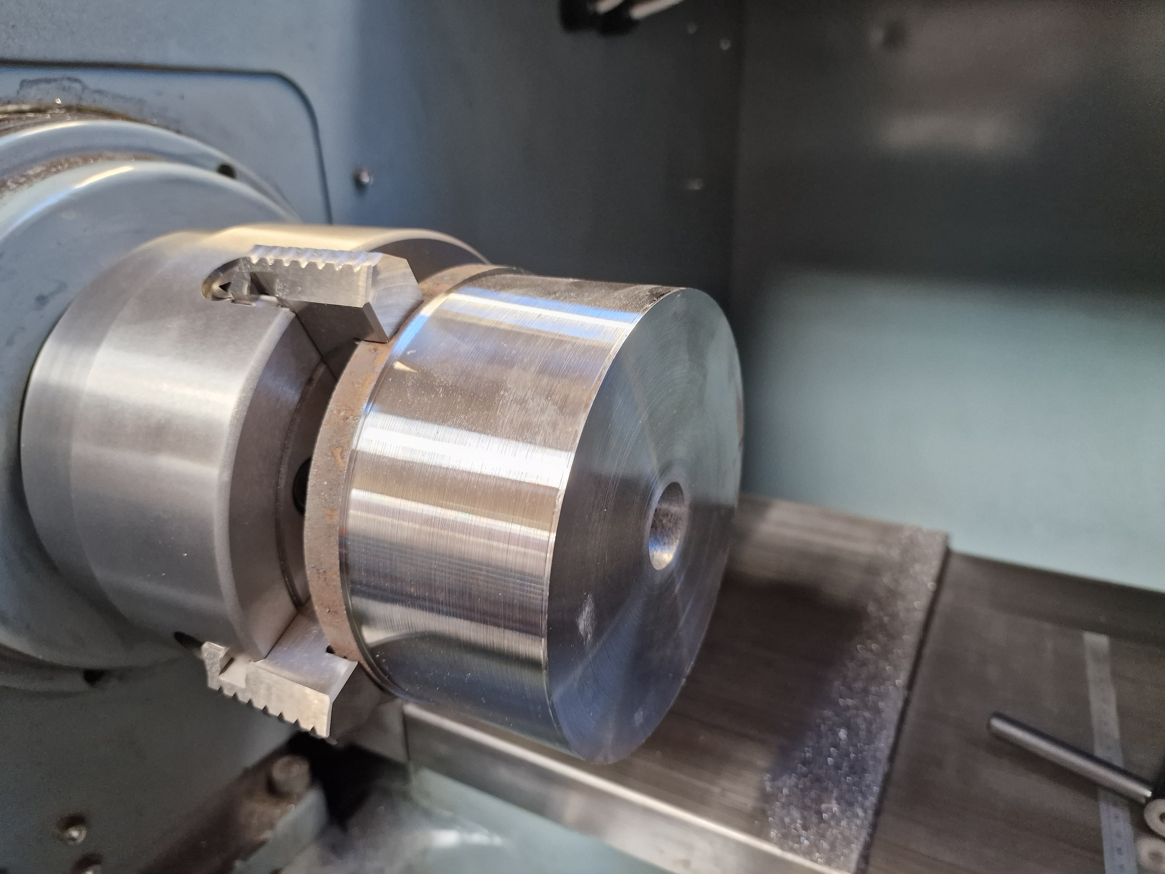
Let's get it mounted in the newly fitted 4-jaw:
It's fairly concentric - or at least good enough, given that I am about to do some roughing out:
New pulley for the motor:
But first, I need to fit a smaller pulley on the motor. Currently I have a 300mm pulley on the motor and 160mm on the motor. That would give the best part of 6000rpm, which would be fine for a small collet chuck but way over the top for a 6" chuck with a max speed rating of 2000rpm. Instead, I'll fit a 118mm pulley on the motor, giving a 3:4 reduction. With a 3000rpm motor, this would theoretically deliver a top speed of 2250rpm, which is better. And when I am down around the 500-1000rpm range, the 4kW motor might stand a chance of cutting some decent chips.
Here's the current setup:
I also have a small pulley behind, although perhaps that was a bit on the small side. I simply chose the smallest that was available for a 28mm shaft.
That's better. The 300mm pulley is still on the motor, but this time it's at the back. The shorter belt worked out well. I calculated the required length quite simply from the difference between the pitch diameters (multiplied by 0.5 x Pi). Good. Now we are finally ready for action.
Let's make some chips then!
The new 20mm boring bar is rather longer than I need, so I will chop it down a bit. Besides, I bought 2 with that in mind. I need about 80mm stickout on this job, so I'll chop off about 50mm.
It's not hardened, so the bandsaw copes fine:
Ready for action:
Off we go:
Quick skim passes in X and Z, then measure it up so I can tell the machine where the tool tip is.
Let's do it:
No video, it didn't happen:
One consequence of taking girlie cuts is that the final finishing pass resulted in some squealing and a slightly patterned finish. If I'm going to do this with indexable tools, I should use a ground / honed insert I suppose. But it's not a functional surface, so I can live with it for now.
A final observation - running the machine with the hydraulic pump off results in a shitty surface finish and hellish chatter. I think we can conclude that although there may be some residual pressure on the turret, it's not enough to ensure rigidity of the tool. That probably shouldn't be a surprise but I was wondering and now I know.
Determining the X offset for drills in the Tree (and other CNC lathes) can be a bit tricky, given that the drill is actually mounted in the turret (cross slide). For this to work without breakage, you need to determine the X coordinate of the drill. This is then entered as the X axis tool offset and ideally it would be constant for all of the drill / boring bar mounts on the turret.
There are a few ways to do this, such as trial and error (by eye etc) ie spinning a piece of stock and moving the turret in X until the tool (drill) tip scribes a point rather than a circle. Another way is to use a concentric indicator, as often used on non-CNC milling machines that don't have electronic probes.
I got one of these before Xmas. Not much more than an ebay / Aliexpress version (and almost certainly Chinese made) but perhaps subject to slightly better quality control.
In simple terms, you probe the outside or inside of a concentric, cylindrical part, then move the turret to minimise the indicated eccentricity. In my case, I can move the turret in X but not Y (ie vertically up and down). Given that there is no evident means of adjusting the turret in Y on the Tree, I have to hope any error isn't significant.
Let's go:
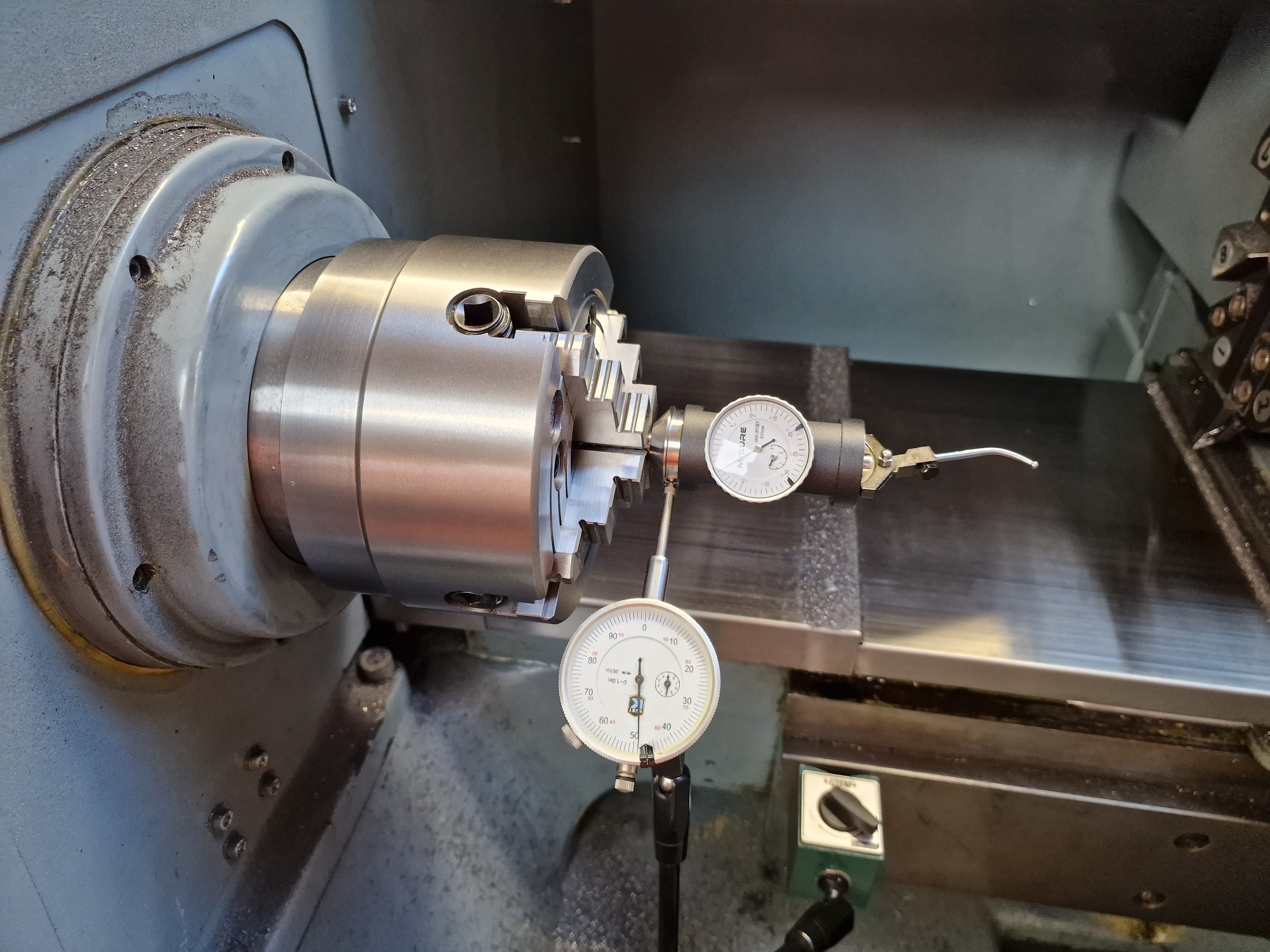
First, set up the indicator so that the main body is deadly concentric. Initially with this Kurt-badged Chinesium thing...
...then with a decent Mitutoyo DTI. I seem to have excelled myself here, as there is no discernible runout shown. That suggests it must be of the order of microns ie far better than this machine could actually attain.
Then, with the probe parallel to the X axis (ie horizontal in my case), spin the machine slowly (~60rpm) and adjust the X axis to ensure the needle is at the same position when the probe is at both front and rear of the bore.
That means the bore is on the spindle axis in terms of the X axis. But next, measuring the error in +/- Y shows that I have around 50-60um eccentricity on each side
Not ideal - but for now there's not a great deal I can do about it. Above all, I don't want to break drills. For accurate bore dimensions, I would normally expect to use a boring bar.
Ideally I would also save the G53 machine coordinate, as this should be a constant, regardless of the reference tool etc.
Saving the drill offset:
This is tool #6:
Here's the absolute machine coordinate for X (-114.342mm):
With tool #6 and its offset selected (T0606) - and X axis zeroed, this is what you'd hope to see. For instance if you loaded a drill in tool #6 and asked for it to positioned in line with the spindle axis:
I may be forced to try out drilling at some point in the near future. No excuse now...
Chip time? Back home now with the new Vertex chuck, so let's get cracking and get it fitted to the spindle. Then I can actually start to machine stuff safely.
Before I get too carried away making chips, let's check the backplate for runout etc in its current state ie as received. I've previously done this and it seems to be fairly well made.
The axial runout on the mating face is pretty good - within 10 microns or so on my Mitutoyo DTI:
Similarly, the radial runout on the external diameter is minimal:
The register is rougher than a bear's arse but it's one surface you'd certainly expect to need to machine for any chuck you plan to fit.
Before running any CAM program, you need to skim the stock in X and Z, to give it some idea where the part is in the current WCS.
Off we go.
No undue excitement or cockups. Having said that, I'm glad I spotted the tool length offset issue in the posted g code (see later), otherwise I'd have had a crash.
Final register diameter is 65mm. I only have 10um calipers but this is a good result.
It's tight enough for the chuck to sit on the register without needing any fixings:
Couple of marks on the spindle and backplate before removing it:
And sure enough, the runout at this stage is minimal:
Fitting the chuck: Now I need to drill and tap the M10 fixings for the chuck. I need to hold the backplate on The Shiz but it's a cylindrical part, so the simplest solution is to bolt it to a piece of stock held in the vise. These existing holes are actually 1/4-20, presumably for a chuck. The threads don't reach all the way to the front face which means I can simply thread the front side M6:
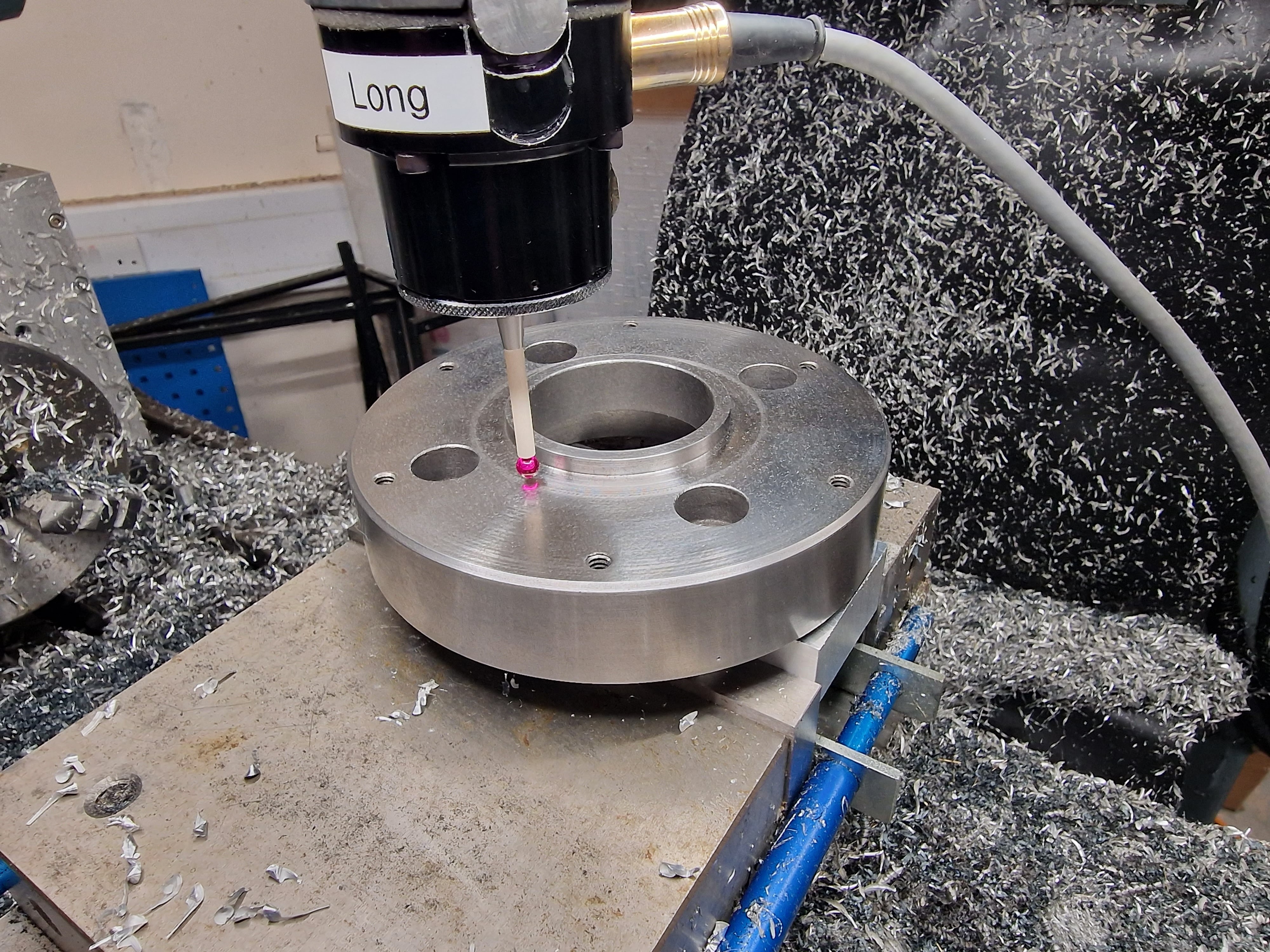
Mounted in The Shiz and ready to probe the bore centre:
First, drill 8.5mm (tapping) through. I have a nice carbide drill for this. Yes, the chuck fixing holes are a bit close to the backplate counterbores but hey. That's a function of the predrilled 1/4-20 holes and I simple went with tapping out the first pair of holes my eye fell on:
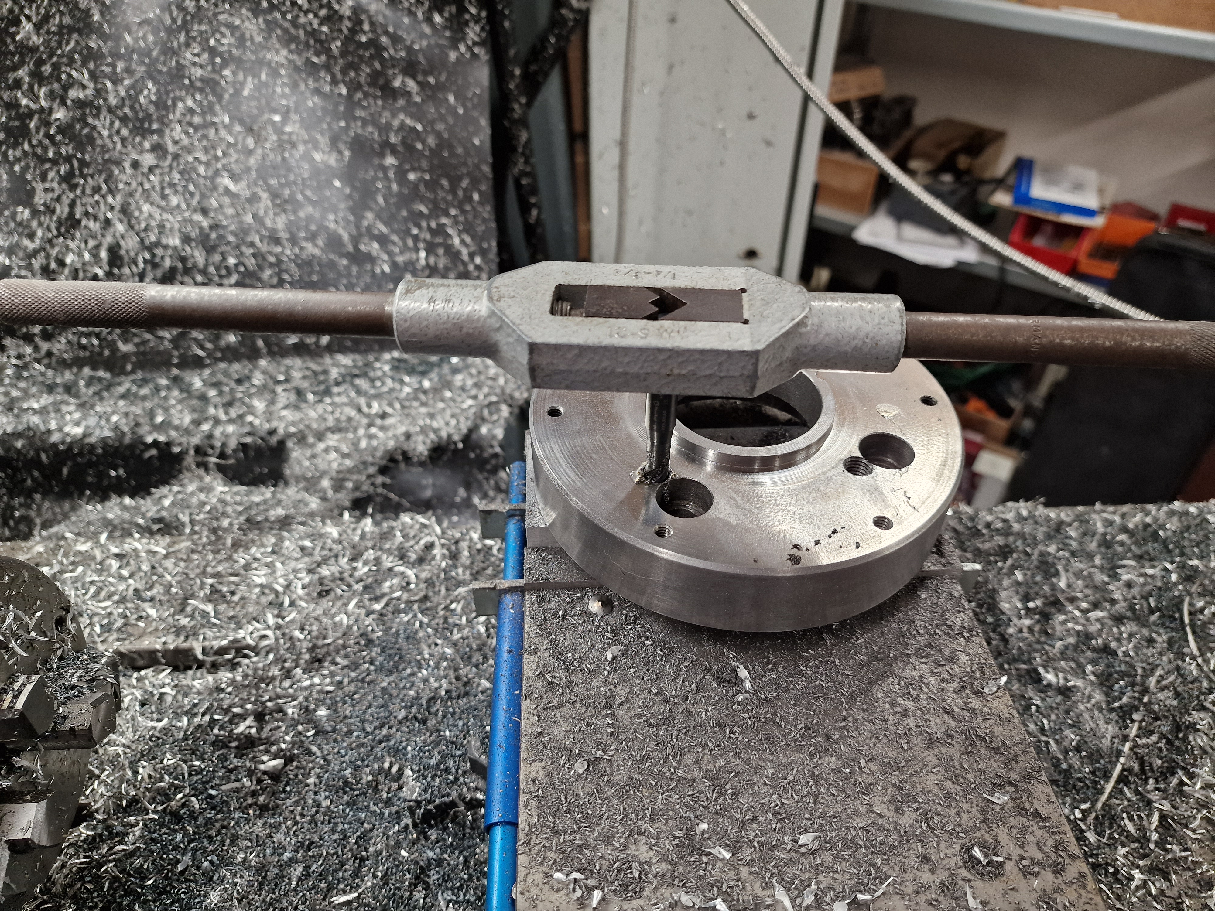
Then tap most of the way in The Shiz and finish using a manual tap wrench:
Finally, bolt the backplate and chuck onto the spindle. Nice:
What do we end up with?
The worst case radial runout at the furthest point from the spindle) is 25um:
And axial runout on the face of the chuck is 10um maximum.
Not bad for starters. Whether it remains as precise as this for any length of time remains to be seen but at least I seem to have made a half decent job of it to start from.
Fusion 360 Post - near cockup on too, length offsets:
The original g-code was missing the red T0303 element on line N19 (see below). Without that, line N15 calls up tool 3 - without an offset. If you tried to run this code, the wrong offset would be applied and a crash into the spindle would be very likely.
;1001
N10 G98 G90
N11 G21
N12 G50 S2000
N13 G53 G0 X0.
;PROFILE ROUGHING2
N14 M0 ;CHANGE TO T3 ON REAR TOOL POST
N15 T0300
;TURRET 102 FOR X POST
N16 G54
N17 G99
N18 G97 S457 M4
N19 G0 X174. Z37. T0303
N20 G50 S2000
N21 G96 S250 M4
N22 G0 Z18.
... etc
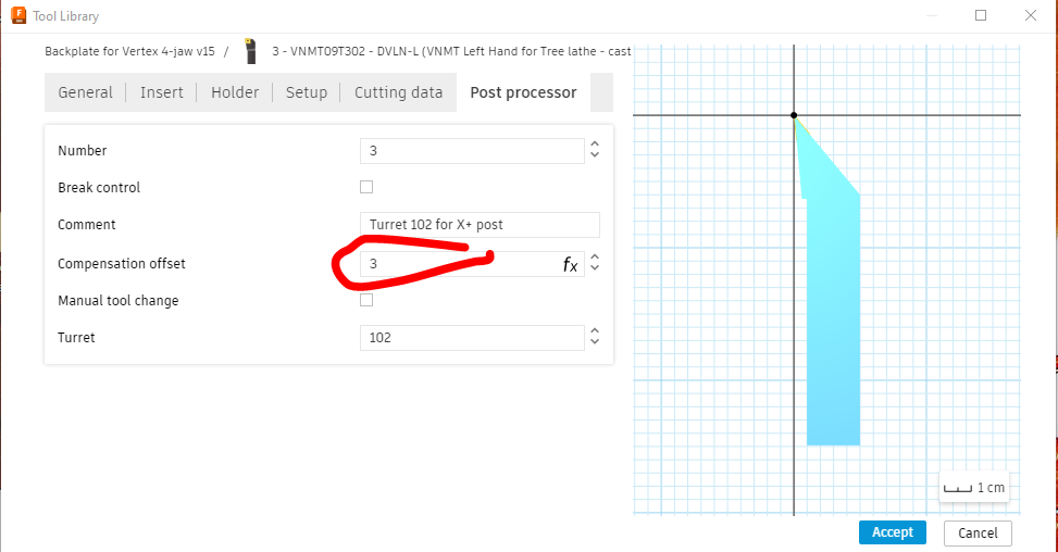
There needed to be a "T0303" somewhere - where had it gone? Turns out this was due to the "compensation field" within the Post Processor settings in the Fusion tool library being set to zero. God knows how this happened - but I think we can safely guess that The Stupid Fat Bloke had been in there playing with the settings:
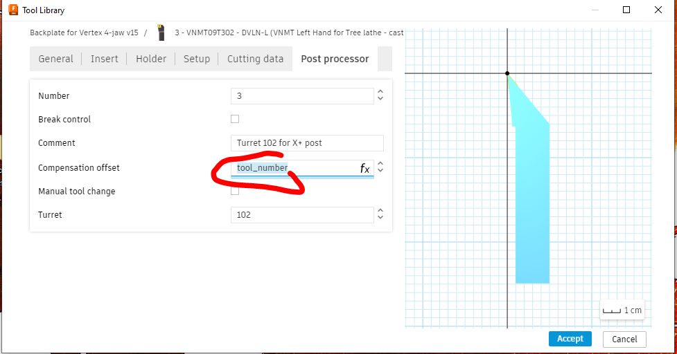
It should set by default (parametrically) to be the same as the tool number, like this:
When set to zero, the "T0x0x" parameter is not generated during post processing. So yes, I've gone through all the tools in the library to find and correct any more examples of this error (2 found), to avoid it biting me in the ass later. We will put that down as a close call. It's A Good Thing I'm starting to get a better understanding of the g code for lathe operations and how it works, otherwise I'd most likely have missed this one....