Wednesday 31 January 2018

Newker 990MDc CNC controller parameter screenshots

Bloody annoying to find that the system parameter backup method (copy parameters to USB) requires a password. None of the std passwords work (NewNew, KerKer etc) so I give up for now. If I'm lucky enough to get any response from my email enquiry, perhaps they will help me but I'm not holding my breath.

So for now I've resorted to taking screenshots with my iPhone. If the worse comes to the worse at least I have a visual record of the parameters as of today. Many of them are still mysteries but at least the system works with these settings.

No words, 'cos each picture says a thousand of them:


Tapping and fitting leadscrew nuts - and flashing up drill block

Leadscrew nuts:

The M12 x 1.5 tap arrived today. It's a machine tap, so was happy to do a full thread in one pass (no second or plug) in the lathe. They both came out nicely:


Fits the leadscrew nicely:


LH handwheel fitted.


RH / powerfeed end:


All works as hoped. There's now negligible backlash. It's quite a change from the massive backlash with the old leadscrew. Will take some getting used to. The Y axis is now "backwards", as the original leadscrew has a LH thread. I'm sure I'll get used to that quickly enough.
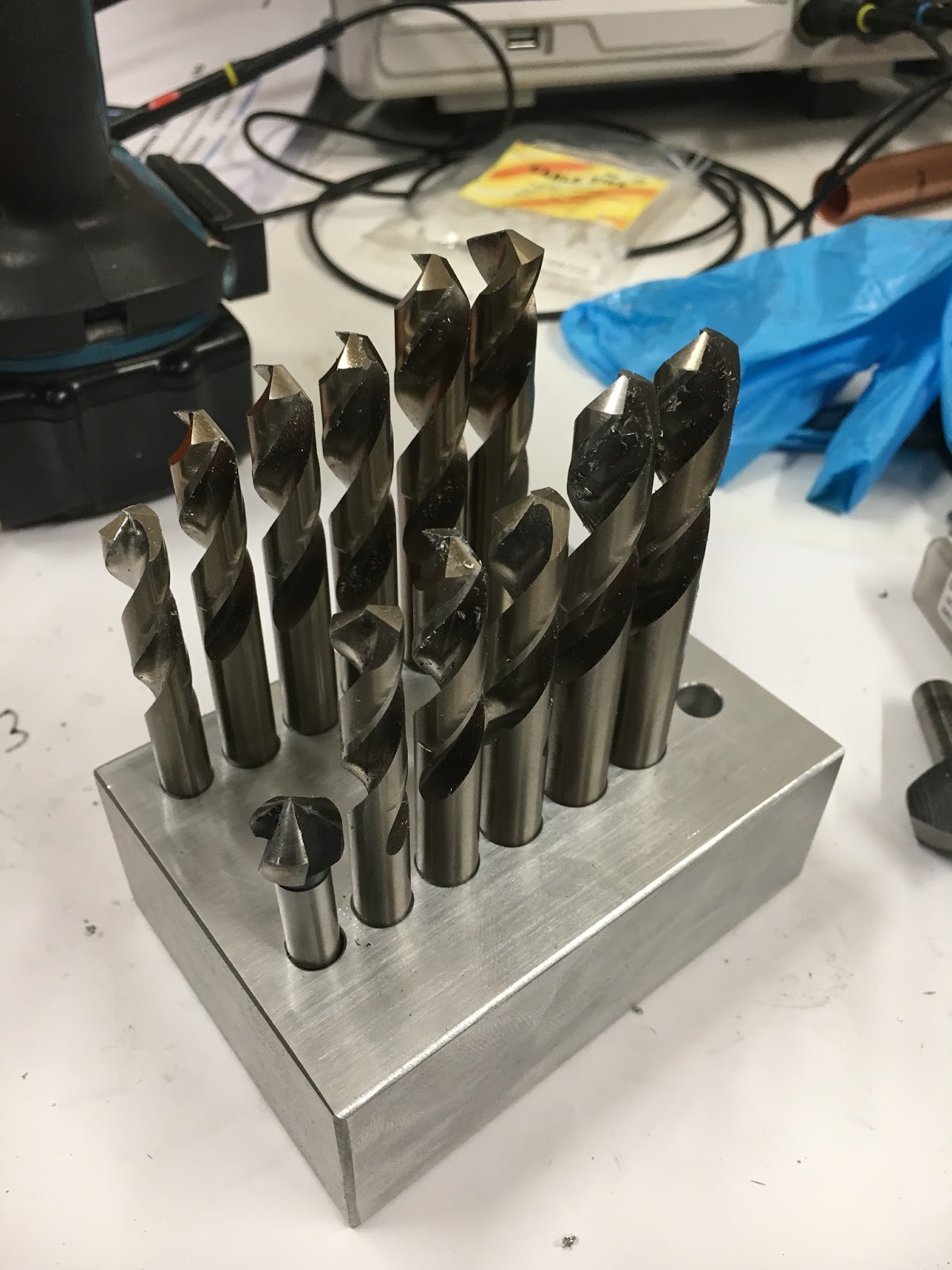
Drill block:

Now that the new leadscrews are up and running I can place the holes for the drill block. Drilled all the holes out 10.0mm and then opened the various holes out with the drills themselves. Then deburred, belt sanded and deburred the surfaces and edges. I am awaiting the 16mm drill chuck (with BT30 taper) which will allow me to drill out the final hole.


The end holes on the front row are for the small and large countersinks: 


There.

Parameter setup for the 4th axis - Newker CNC controller

Loads of parameters in there that seem to relate to various speeds and ratios:

  • The axis speeds are in mm/min or degrees/min (not degrees/second!!), so the correct number would be of the order of 1200-1400, given that the driver and motor bomb out at about 15 seconds per turn.
  • The units are important too. I have 2000 steps per turn set up on the stepper driver and the controller seems to generate 4 pulses per "step", so I need 8000 on the numerator and 1900 on the demominator (# in "axis" parameters). Not clear quite how all that works but certainly, the indicated units for the A axis correspond with degrees movement on the table.
  • The A axis acceleration for the "rampit" (rapid) homing move works nicely when you ask it to home the A axis. If you set the number too low, it takes forever to get up to speed.
Must make some simple g code so I can test it out to see if it behaves sensibly.

Tuesday 30 January 2018

Grow a pair!

I designed the new X axis ballscrew ends with an M12 x 1.5 thread (aka one of the "metric fine" pitches). Don't recall why, but that's not the point. What is the point is that I don't have any nuts that size, nor any taps. So I ordered a spiral flute tap (YG-1 brand) from Cutwel that should arrive tomorrow in the post. Before I can use it, I'll need to make up a couple of nut blanks.

Got some nice looking hex bar some time back in Canada. Seems like the local equivalent of our EN1a ie cuts like butter and leaves a very nice finish. I used it to make replacements for some of the large bolts on the Blidgeport. Looks spot on in terms of dimensions for this job which is handy, given that I don't seem to have anything else to choose from.

This first nut is what secures the hand wheel on the RH of the ballscrew when there is a power feed unit fitted. Due to the additional length of the bevel gear drive, this nut has to extend into the bore of the handwheel. It comes with the power feed unit. So it needs a reduced section as shown. I've just copied the length of the shoulder it by eye, by holding the original alongside. The original has a different thread obviously - some sort of Mercan pitch (UNF?).


It's sensible to chamfer the edges before parting off. I'm using the Korloy KGT parting / turning tool here to chamfer this one and the start of the next one at the same time:


And at the other end of the ballscrew is a plain nut. I've just chamfered the end here. The through hole is the tapping drill for M12 x 1.5 ie 10.5mm.


Here they are. Original Mercan nut at the left, New blanks alongside. Ready for threading.

There.

Monday 29 January 2018

New stepper motor for the 4th Axis

The new stepper arrived today - and so did the Taper Lock pulley. Time to check it works with the Leadshine driver and see if it is man enough to drive the rotary table.

Quick lashup on the bench. The cable hanging off the bench comes from the CNC controller. The handwheel MPG generates pulses to drive the Leadshine driver. That all seems to work.


This is the original motor. I need to remove it and modify the new motor to fit the existing register and drill / tap new fixings.


The flat bracket is welded to the baseplate, so not much danger of boring it out to suit the new motor. Instead, I'll dismantle the motor and turn down the register to suit the hole in the bracket - the diameter is 56mm. First, remove the end of the motor so I can mount it in the lathe:


Mount it in the 4-jaw and clock it up within a few thou. Not critical at all but why not do it right!


Also check it's roughly square to the spindle:


Double check:


Done - no hands! A nice tight fit in the hole:


Drill and tap 4 new M6 holes:


China's finest - not much in a stepper motor....


Reused the same bolts I used for the original motor:


It's now 19:24 ratio with the new pulley. The belt length is a bit more sensible.


Seems able to run the table at a usable speed. It's not a servo so the top speed will be a bit limited. Need to set up the controller parameters now....

Final assembly and test of the spindle nose adaptor - RESULT!!

After the recent distraction caused by the 3D scanner, resurrecting the 3D printer and buggering about with the throttle bodies for my Honda...