Tuesday 29 March 2022

Design spindle adaptor - A2-5 to D1-3

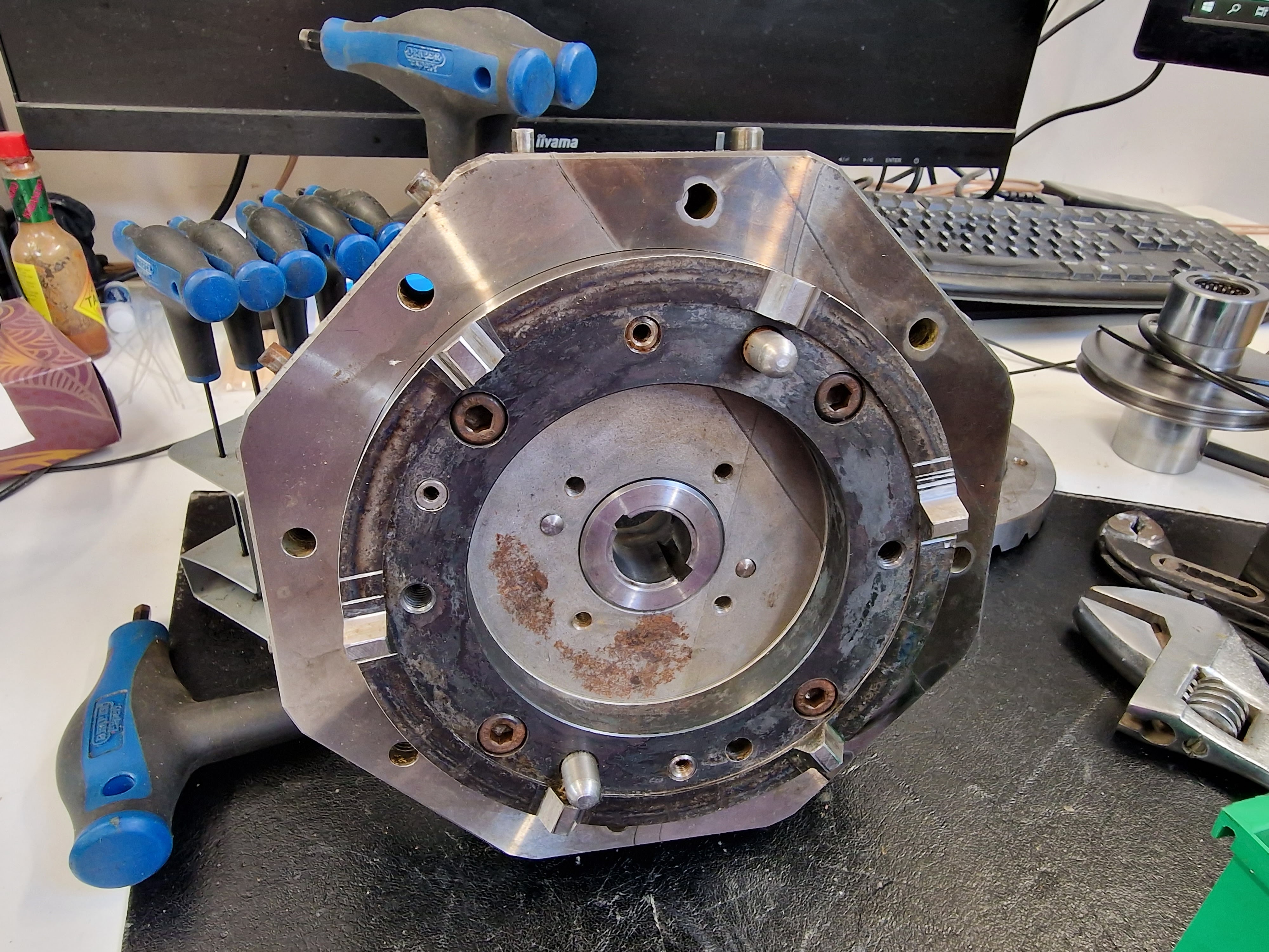
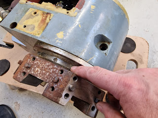
I bought a cast iron backplate for the Tree from ebay, as this was the only example I could find. My hope was that I'd be able to bodge it so that it would allow me to fit my collection of D1-3 "Camlock" chucks, faceplates etc to the Tree rather than have to fork out for a whole new set. It may turn out to be usable in some form but there's clearly not enough meat on it to be able to use it for an A2-5 to D1-3 adaptor as such. I'm going to have to make my own from barstock.

Let's dig out the spec for the A2-5 and D1-3 spindle noses. They are both specified in BS ISO 702 (parts 1 and 2). 


They are both conical couplings but the A series use bolts, while the D1 series use cams to hold the chuck in place. 

  • A1-x series have 2 bolt circles
  • A2-x series have one (outer) bolt circle.
  • The second number denotes the size (diameter). 
  • They all have 7.125 degree cone angle (1:4 taper, tangent 1/8)
  • Mine is an "A2-5" ie one bolt circle and 133mm diameter.
As for the D1 series, the nose tapers and diameters are the same as the A series. So you could remove the cams from a Camlock chuck and it would fit an A series nose. In my case, I have size 3 Camlock chucks and a size 5 nose, so the cones are different diameters. Never mind.

A series:
Mine only has the outer bolt circle. Note the drive pin and the fact that there are 12 fixings, so it's possible to use either 3 or 4 bolts if preferred. If you have a 3 -jaw or 4-jaw chuck or a D1-3 adaptor, the fixings won't need to get in the way.


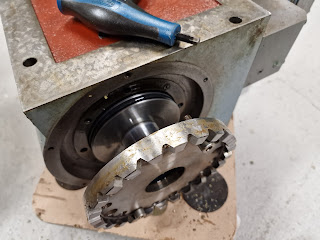
Here are the cams. The form on the LHS is the "size 3" used on the D1-3.


CAD modelling:

Let's create something to work with. To start with, the A2-5 spindle nose used on my machine. Note that in my case, I have 7/16" UNC threads, not M10. Other than that, the dimensions all seem to agree.

Now for the "standard" D1-3 spindle nose. This is what my chucks etc would expect to encounter eg on my Bantam.

Clearly when you mount the D1-3 nose on front of the A2-5 nose, more meat needs to be added to accommodate the taper nose of the A2-5. Also, the A2-5 fixing bolts would fall outside the D1-3 profile, so the diameter will need to be increased. At this point, it's no longer the "standard" spindle nose, so I have freedom to redesign as required. This also includes the cams, which need to be lengthened. And I can change / move the retaining screws.

Here we go - rear view:


Front view:


Front view, mated with A2-5 spindle nose:


And here's the modified cam:

Let's order some steel for the adaptor. I'll go for 4140 (aka EN19T). It needs to be 135mm diameter by 60mm long, so 140mm x 70mm it is - and 2 off in case I fuck up the first attempt.....

Saturday 26 March 2022

Starting to rebuild the turret - and A2-5 spindle nose threads

I'll start by reassembling the locating plate onto the turret body. But first, I'll need to remove one of the 3 dowel pins. There's no way to drive all 3 pins in together.


I don't have a slide hammer, so an adjustable spanner pivoting on a broken 4mm end mill does the trick. The thread is M5, FYI.


That's better.


Then refit the shaft bushing:


This is the sequence of assembly. The piston pulls the turret against the housing.


Fitting the seal ring.


You can see how the whole shaft assembly shifts left and right under hydraulic pressure. The index plate on the right is held solid to the main body. The gear and ratchet plate slide with the piston.


I can't refit the turret until the replacement o-ring arrives. The outer sealing ring and o-ring is here on the right.


The main piston is back in place. 


The hydraulic motor and the rear roller bearing back in place.


The next part to go on is the index plate with its new o-ring. That will have to wait for now....


Spindle nose threads?
Yes, the A2-5 spindle nose has 7/16" UNC threads but some specs show that an M10 thread may be used. I have some 7/16" BSW taps which have the same 14TPI pitch but a different thread angle (55 rather than 60 degrees). I now know the correct fasteners to use for this spindle and clearing out the threads is a useful activity.


Well that's all I can do on the turret for now.....

O-ring selection and replacement

So I need to replace the static o-ring seal. Some background reading: Parker o-ring handbook. Look a section 5. Useful application info - but of course it's Mercan ie imperial units.

Barnwell o-ring catalogue including piston groove dimensions.

George Lodge Direct website.

The static o-ring seems to have become shredded, presumably during insertion last time round. This would have leaked like a sieve if I'd tried it.


The dynamic seal on the piston looks fine. 


Thin o-ring:
  • Bead - 3mm diameter
  • Piston - 110mm diameter
  • Groove - 105.5mm diameter (this is the required ID dimension) 

Fat o-ring:

  • Bead - 5.5mm diameter
  • Piston - 110mm diameter
  • Groove - 100mm diameter (this is the required ID dimension)
So I require an o-ring with an ID of 105.5mm and a bead diameter of 3mm.

Like this from George Lodge Direct Consider it ordered...

Sunday 20 March 2022

Dismantling the tool turret

The servos and spindle motor won't arrive for another couple of weeks and there's plenty left to do besides the axis and spindle drives. I have a fair idea how the turret works but I'll need to fully sus it out and also rebuild it anyway. The exploded parts list gives an idea what's in there but it's almost impossible to figure out the correct sequence to follow for disassembly.  


Sod it, let's dive in here. I know somebody's been in here before because there's a homemade tool for removing the castellated nut in the centre of the turret. So let's start here.


With the turret removed, we can see the indexing scheme. The rear of the turret has a "locating plate" with 6 features that mate with....


18 features on the stationery "index plate". Due to the additional action of the pins on the locator plate, it only actually mates in 6 positions.


The plate is held in place with 4 screws and 3 dowel pins. Luckily there are also threaded extraction holes for jacking the plate away from the turret body.


The cylindrical component provides a surface for a sealing o-ring to work against. It's simply held in place with 4 screws.


Around the back of the mechanism, there's the hydraulic motor and a 6 position rotary switch. That needs to come off for safe keeping. There are also a couple of wires from the microswitch that indicates when the turret is locked in position.


The locking pawl is activated by a hydraulic piston.


There's a roller thrust bearing here.


The index plate is held by 4 screws.


Again, there are threaded holes for extraction.


Here is the pawl mechanism.


That's pretty much it. Now what have we found?

The static seal between the index plate and the main housing has been shredded. This must have happened last time it was reassembled. That doesn't inspire confidence, so I'll need to carefully examine the rest of the seals.


This is the piston seal. Looks fine, thankfully. And the bore seals in the main housing and index plate look fine, too. So I will need to replace the shredded o-ring but none of the others from what I can see.


Here are my measurements:


Final assembly and test of the spindle nose adaptor - RESULT!!

After the recent distraction caused by the 3D scanner, resurrecting the 3D printer and buggering about with the throttle bodies for my Honda...