Thursday 30 December 2021

Finishing off the "front mounting" ballscrew bracket etc for the Bantam

Having machined out the cavity, I need to flip it over and finish off the other side. It's quite a wide bracket, so only just fits in the 6" vise jaws. 

Let's go...


Getting there...


Counterboring for the cap screws


Roughed out with 1mm stepdowns


After finishing with 3mm radius cutter:


8mm carbide drill all the way through...


Machine tapping the M6 threads


There. Fits nicely and bolts up without needing any buggerage.


Now for the drive bracket that connects the ballnut yoke to the underside of the saddle.


Sorted


Now I need to machine the matching M6 fixing holes on the underside of the saddle body. This requires the vise jaws to be fitted on the outside positions: 


This is where it should end up:


Drill 5mm


Tap M6


It even bolts up correctly:


Now let's look at the saddle gibs...

Thursday 23 December 2021

Bantam - changing to a front ballscrew concept

How's the redesign going, Fatty?

It only took a few hours(!) to create a new assembly with the ballscrew assembly mounted on the front of the machine, close to where the original leadscrew and rack would have driven the saddle. Obvs, I've tried to reuse as many of the original parts as possible - where it makes sense of course.

Here's what I've got, in a sort of "ghost view":


The servo motor bracket and mating encoder bracket are unchanged, as is the travelling ballnut yoke. I had to model the underside of the saddle to enable me to design a suitable mating bracket to engage with the ballnut yoke and connect to the bottom of the saddle. 


There's a new bracket where the original leadscrew / power shaft bracket used to be. That's the main challenge here, work-wise, as it's going to require a fair bit of metal removal. 


Rather than fuck about with poncey 10mm carbide cutters, I'm going to use my 50mm Korloy face mill. It's easy to forget that these are intended for bigger jobs than simply facing off stock. I have a suitable piece of 1.5" x 2.5" loominum (6082?) that will be spot on for the job, so here's the work set up with that stock. 


Same toolpath in simulation:


Bottom line - am I expecting a silly / unrealistic spindle power requirement with these settings? Given that this is expecting to take 18 mins to complete, it doesn't sound completely daft. I've got the best part of 3kW available, so I should be trying to make use of that.

Here's my spreadsheet with the settings I've chosen. For no good reason, I've dialled back from the original 10mm depth of cut (roughing stepdown). And the 0.1mm feed per tooth is at the light end of the typical range (0.1 - 0.5mm), so I'm not exactly pushing things here, even at 2000rpm. 1.3kW estimated power should be well within the machine's capability


OK, so let's prepare some stock and set to.


It was covered in dried coolant and swarf. Amazing what a bit of Swarfega will do!


Square it off to length (229mm)


Nom, nom - let me at it! Nice sharp APGT1604 inserts on Korloy face mill...


That is fairly noisy but nothing alarming. Pretty sure I could at least double the MMR eg by upping the spindle speed or increasing the feed per tooth or both.


That makes some decent looking chips.


This was a 3D Adaptive toolpath with zero "stock to leave". The bottom surface comes out nice and flat due to the wiper feature on the inserts. The sides are non functional and barely visible, so I don't see any justification for any kind of finishing operation, so that will do for this side.


The angled face actually has 1mm stepdowns but from a distance you can barely see the steps anyway.


Now I need to flip it over and machine the other side...

Saturday 18 December 2021

Bantam carriage / bed adjustment - whoa - design rethink??

Wossup now, Fatty?
There's no point me getting too carried away getting the Bantam all boxed up and tidied up before I've made a decent job of adjusting all the various gib strips etc. Currently, it's functional but when I last assembled it all, I simply bolted it all together to check out the function, rather than set it up finally for accuracy. That time seems to have arrived now.

The cross slide is fairly straightforward and can be adjusted without any disassembly being required - you can loosen off the locking screws and adjust the gibs from the top and side of the cross slide. The top / compound slide is even simpler, as I'm not using it any more.

But the bed ways on this machine are the classical "flat and vee" design. The vee ways provide radial(?) location of the saddle (ie in the X axis direction, the direction the cross slide moves in) as well as vertical location (the weight of the saddle and cross slide assembly plus the machine loads), while the flats at the rear simply provide vertical location.

I haven't modelled the front saddle gib (and its friend, the saddle lock) yet but I've sketched it in to this screenshot (red).The saddle ballscrew that drives the saddle up and down the bed is a funny pink colour - it's also quite a way from the front vee.....


What's the problem with that?
One drawback of my choice of location of the ballscrew at the rear of the saddle is the twisting moment that results from the distance of the ballnut from the vees. On the conventional machine, both the leadscrew and the feed rack are almost directly underneath the vees, resulting in minimal moment. Obviously, if I have any loose play in the vee, the whole saddle will want to go out of square when any kind of load is applied through the ballscrew / ballnut.

In order to minimise the movement that would (will!) arise from this effect, I'd need to have the front gibs nipped up pretty tight. The vees are something like 90 degrees included angle, so will want to bind when a twist is applied. This all feels rather suboptimal.

In fact, I'd say this was a bit of a serious fuckup. I really can't see any sensible way of making this work acceptably. Time to stop and have a (re)think?

How did it end up like this?
It's the usual story. I wanted to retain as much of the original features and functions of the Bantam as possible. This meant fitting the X axis (longitudinal) ballscrew at the rear of the machine, even though I could see that wouldn't be quite ideal.

However, having got the system up and running, I've now removed the apron with its cross slide and saddle handwheels, as they add nothing except inertial mass and generally get in the way. This leaves the whole of the front of the machine clear after all. I really don't see myself refitting the manual controls at any point, so perhaps this is the time to have a bit of a rethink about the X axis ballscrew location. Really? Dear god, are you taking the piss?

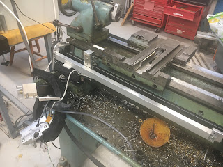
Let's strip things down:
See what I mean - things are nice and simple with no apron:


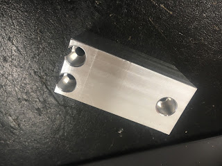
Here are the front gib strips (looking up from below). The RH one is also the saddle lock, hence the slit.

The operation manual says that the only way to adjust the front gibs is by machining them. WTF?? Certainly, loosening the carriage lock results in noticeable vertical movement when I try to lift the front of the saddle. That's not ideal but there's no simple workaround. Bollocks - some sort of adjuster may need to be crafted up here.


Round at the back:


These counterbored fasteners (3 off) are the lock screws that hold the rear gib strip once the vertical clearance has been adjusted.


Let's remove the rear swarf guard thing and strip the gubbins off so we can get a closer look.


That's easier to see. First, off with the rear ballscrew guard, exposing the servo drive, rear limit switch and encoder head.


The cross slide simply slides off once the 2 ballnut fasteners are removed. That Oldham coupling will be coming off, now that I've jettisoned the cross slide handwheel after all.


The motor comes off next


I should really remove the limit switches before they get ripped off by The Stupid Fat Bloke.


Rear limit switch:


Front limit switch


There. Just the saddle remains now:


The rear gib strip assembly can now be seen properly, under the saddle:


Here's the rear gib assembly after removal. It's actually lying on its side. You can see the 3 height adjusters, as well as the 3 fasteners that secure it to the underside of the saddle.


You can see how the height is adjusted. There's no mention of this in the manual and even the exploded parts list doesn't really help


Oops. We seem to be undergoing a surprise audit.


It's always good to get the approval of the workshop supervisor. I think that was a nod, so all seems to be in order.


Enough?
Bollocks - let's also whip off the X axis ballscrew and ballnut. In for a penny, in for a pound! Obvs at this stage I'm going to be fucked if it turns out I need to turn anything. Perhaps I can refit the apron if I desperately need to do any manual ops on the lathe, otherwise I will have to rely on The Shiz for everything.

Let's do some CAD work to figure out a better solution.....

Thursday 16 December 2021

LinuxCNC lathe post - silly G28 problem with the official Autodesk post processor

What the matter?

The official post processor available for download from the Autodesk post processor library for use with LinuxCNC turning seems to work reasonably well but when you select the G28 safe retract option within the post processor dialogue box, the resulting g-code defines the retract coordinates in U & W rather than X & Z. 


This is what we get at the end of the file, where we want the machine to do a safe retract:

N592 M9
N593 M5
N594 G28 U0.
N595 M30
%

This is what we need:

N592 M9
N593 M5
N594 G28 X0.
N595 M30
%

Unfortunately, LinuxCNC doesn't recognise movements in U & W, so it barfs when you try to run that line of code. However, when you select the G53 alternative scheme for safe retract, no problem. Hmm.

Let's look at the post processor script (the current version is r43470):

 // format home positions
  for (var i = 0; i < retractAxes.length; ++i) {
    switch (retractAxes[i]) {
    case X:
      words.push((method == "G28" ? "U" : "X") + xFormat.format(_xHome));
      retracted[X] = true;
      xOutput.reset();
      break;
    case Y:
      if (yOutput.isEnabled()) {
        words.push((method == "G28" ? "V" : "Y") + yFormat.format(_yHome));
        yOutput.reset();
      }
      break;
    case Z:
      words.push((method == "G28" ? "W" : "Z") + zFormat.format(_zHome));
      retracted[Z] = true;
      zOutput.reset();
      break;
    case XZ:
      words.push((method == "G28" ? "U" : "X") + xFormat.format(_xHome));
      words.push((method == "G28" ? "W" : "Z") + zFormat.format(_zHome));
      retracted[X] = true;
      retracted[Z] = true;
      xOutput.reset();
      zOutput.reset();
      break;
    default:
      error(localize("Unsupported axis specified for writeRetract()."));
      return;
    }
  }
  for (var i = 0; i < words.length; ++i) {
    switch (method) {
    case "G28":
      writeBlock(gFormat.format(28), singleLineRetract ? words : words[i]);
      break;
    case "G53":
      gMotionModal.reset();
      writeBlock(gFormat.format(53), gMotionModal.format(0), singleLineRetract ? words : words[i]);
      break;
    default:
      error(localize("Unsupported safe position method."));
      return;
    }
    if (singleLineRetract) {
      break;
    }
  }
  singleLineRetract = false; // singleLineRetract reset
}

The red lines will cause "U" and "W" prefices to be generated if G28 is chosen from the dialogue or "X" and "Z" in any other case. Given that the only alternative selection is G53, this explains what we are seeing ie either G28 X0 W0 or G28 U0 W0 etc.

FYI, the "?" ternary operator allows selection of one of two options according to the condition of the first term. So if the variable "method" has the value "G28", the prefix "U" or "W" will be chosen, otherwise, we will get "X" or "Z".

In the previous-but-one version of the LinuxCNC post (r43417), we saw different content - and furthermore it actually output the correct G28 X0 Z0 code. 

  // format home positions
  for (var i = 0; i < retractAxes.length; ++i) {
    switch (retractAxes[i]) {
    case X:
      words.push((method == "G28","X") + xFormat.format(_xHome));
      retracted[X] = true;
      xOutput.reset();
      break;
    case Y:
      if (yOutput.isEnabled()) {
        words.push((method == "G28" ? "V" : "Y") + yFormat.format(_yHome));
        yOutput.reset();
      }
      break;
    case Z:
      words.push((method == "G28","Z") + zFormat.format(_zHome));
      retracted[Z] = true;
      zOutput.reset();
      break;
    case XZ:
      words.push((method == "G28","X") + xFormat.format(_xHome));
      words.push((method == "G28","Z") + zFormat.format(_zHome)); 
      retracted[X] = true;
      retracted[Z] = true;
      xOutput.reset();
      zOutput.reset();
      break;
    default:
      error(localize("Unsupported axis specified for writeRetract()."));
      return;
    }
  }
  for (var i = 0; i < words.length; ++i) {
    switch (method) {
    case "G28":
      writeBlock(gFormat.format(28), singleLineRetract ? words : words[i]);
      break;
    case "G53":
      gMotionModal.reset();
      writeBlock(gFormat.format(53), gMotionModal.format(0), singleLineRetract ? words : words[i]);
      break;
    default:
      error(localize("Unsupported safe position method."));
      return;
    }
    if (singleLineRetract) {
      break;
    }
  }
  singleLineRetract = false; // singleLineRetract reset
}

So somebody somewhere in Autodesk managed to fuck this bit up. Nobody knows why of course. The fix is to paste in the red lines from the first section into the latest post processor (ie in place of the red text in the second).

Note that there's also some "orphan" content referring to the Y axis (in blue) that has clearly been left over from a milling post. It shouldn't have any effect but it's not fully approved.

Good to have fixed that. I'd much rather use G28 than specify G53 machine coordinates.

Wednesday 15 December 2021

Touch screen misbehaving with Linux Mint 20.....

More toys, fatty?

Yes, after waiting (im)patiently for a cheap touchscreen display to come up on ebay, I finally gave up and got a Hannspree HT225 touchscreen display for the LinuxCNC Bantam. I could have bought a used one with no warranty for perhaps half the price but a new one wouldn't exactly break the bank and most come with 2-3 years warranty.

Most of the Linux GUIs are optimised (intended) for use with a touchscreen and it's a PITA having to walk over to the bench to grab the mouse each time I want to start and stop the Bantam when in manual mode.

This thing has a built-in PSU and a host of video inputs. And I checked it has a capacitive touchscreen, rather than an IR version. The Shiz has an ASUS All-In-One PC with IR touchscreen and I ended up disabling the touch function due to the endless issues I had with dust on/in the touch system and interference of sunlight with the damned thing.

The reviews seem to suggest these will work out of the box with Linux Ubuntu, Mint etc, so what could possibly go wrong? There's only one way to find out....

Well - does it work then?

Sure enough, it sparked up immediately and the touchscreen interface even worked without requiring any driver buggerage. Very pleasing. Except.....with 2 displays to deal with, the mouse cursor moves across BOTH screens when you drag your finger from one side of the touchscreen to the other. WTF??

Luckily, this isn't an obscure problem, so there are various posts showing how to scale the horizontal movement across just one display. Like this one.

This line shows you what input and output devices are configured:

 muzzer_linux@LinuxCNC:~$ xinput
⎡ Virtual core pointer                                                 id=2    [master pointer  (3)]
⎜   ↳ Virtual core XTEST pointer                                id=4    [slave  pointer  (2)]
⎜   ↳ Logitech Wireless Mouse                                   id=10    [slave  pointer  (2)]
⎜   ↳ Logitech K540/K545                                           id=11    [slave  pointer  (2)]
⎜   ↳ Weida Hi-Tech CoolTouchR System Mouse        id=12    [slave  pointer  (2)]
⎜   ↳ Weida Hi-Tech CoolTouchR System             id=13    [slave  pointer  (2)]
⎣ Virtual core keyboard                                              id=3    [master keyboard (2)]
    ↳ Virtual core XTEST keyboard                             id=5    [slave  keyboard (3)]
    ↳ Power Button                                                      id=6    [slave  keyboard (3)]
    ↳ Video Bus                                                            id=7    [slave  keyboard (3)]
    ↳ Power Button                                                      id=8    [slave  keyboard (3)]
    ↳ Sleep Button                                                       id=9    [slave  keyboard (3)]
    ↳ Logitech K540/K545                                           id=14    [slave  keyboard (3)]


The CoolTouch device with id=13 is the touchscreen input device.

Next, this line tells you what displays are connected and which video mode they are in:

muzzer_linux@LinuxCNC:~$ xrandr
Screen 0: minimum 320 x 200, current 3840 x 1080, maximum 16384 x 16384
VGA-1 connected 1920x1080+1920+0 (normal left inverted right x axis y axis) 531mm x 299mm
   1920x1080     60.00*+
   1600x1200     60.00  
   1680x1050     59.95  
   1280x1024     75.02    60.02  
   1440x900      59.89  
   1280x960      60.00  
   1152x864      75.00  
   1024x768      75.03    70.07    60.00  
   832x624       74.55  
   800x600       72.19    75.00    60.32    56.25  
   640x480       75.00    72.81    66.67    59.94  
   720x400       70.08  
DP-1 disconnected (normal left inverted right x axis y axis)
HDMI-1 connected primary 1920x1080+0+0 (normal left inverted right x axis y axis) 477mm x 268mm
   1920x1080     60.00*+  50.00    59.94  
   1920x1080i    60.00    50.00    59.94  
   1680x1050     59.88  
   1400x1050     59.95  
   1600x900      60.00  
   1280x1024     75.02    60.02  
   1440x900      59.90  
   1152x864      75.00  
   1280x720      60.00    50.00    59.94  
   1024x768      75.03    70.07    60.00  
   832x624       74.55  
   800x600       72.19    75.00    60.32    56.25  
   720x576       50.00  
   720x576i      50.00  
   720x480       60.00    59.94  
   720x480i      60.00    59.94  
   640x480       75.00    72.81    66.67    60.00    59.94  
   720x400       70.08  

So the fix is to map device 13 to dispay HDMI-1 like this:

muzzer_linux@LinuxCNC:~$ xinput map-to-output 13 HDMI-1

...and whoopee shit - it works!

Making it last:

Of course, when you reboot, that setting is lost and the script doesn't magically rerun itself without some help. 

There are any number of Linux power users offering baffling "power user" solutions to this question. All I want is for this script to be run automatically at startup. Shit like this:

https://askubuntu.com/questions/1085835/how-can-an-xinput-command-be-run-automatically-when-the-system-is-started-in-ubu

https://askubuntu.com/questions/919054/how-do-i-run-a-single-command-at-startup-using-systemd

https://askubuntu.com/questions/814/how-to-run-scripts-on-start-up

FFS!

But yes, in fact there is a simple way to do it. In System > Startup Applications, you can either select a program to run at startup or (if you prefer) a script. 

Like this:

Oddly enough, I've called mine "Touchscreen calibration". The script appears to run at startup (with a carriage return) and seems to do the trick.

Final assembly and test of the spindle nose adaptor - RESULT!!

After the recent distraction caused by the 3D scanner, resurrecting the 3D printer and buggering about with the throttle bodies for my Honda...