Wednesday 22 November 2017

Boxing up The Shiz

I've lost a fair bit of time over the last week or so due to some buggerage with work - or more accurately the impending cessation of work with the current employer. I've pretty much done what was required for them and although it was described as a permanent position, if they don't decide to make any follow-on new products, it would be rather extravagant to keep paying me. And being Chinese it seems that the notice period in the written contract is open for interpretation. I suppose you could say it should come as no surprise, having seen it so many times before. Still, nobody died and I remain employable, so the next challenge lies in wait for me out there. But the bottom line is that I've been busy buggering about with CVs and agencies - and also feeling a little less motivated than ideal.

However, there has been some progress, just not as much as I'd normally expect. The framework for the swarf / coolant enclosure is coming along and is almost ready to come off for final welding up.

This is the frame for the hinged door. The idea is a direct copy of Threadexpress's enclosure design. There will be a fixed see-through polycarbonate panel in the hinged frame and another, sliding one to cover the remaining opening. 


The whole thing goes up and down with the knee, so there needs to be some form of anchorage at the back of the knee. This is a great excuse for butchering the machine by drilling and tapping holes in it:


This was the state of play yesterday evening:


Before getting some more time in the workshop this afternoon (only an hour at the most), I also had a go at levelling the kitchen floor with some of that self-levelling screeding compound. Worked quite well. Before dumping the stuff on the floor, I used a long spirit level to position some screws (in wall plugs) at various places across the floor. By screwing them in and out (down and up), I could see what the required level should be. I marked them out in yellow to avoid tripping over them.


Now for the mix and pour. This is the result of 4 bags:


It's set now and is fine to walk on. I'll tackle the other side of the kitchen next time, possibly tomorrow.

Monday 13 November 2017

Leadshine DM556 stepper drive for 4th axis - real or fake??

The "Leadshine" DM556 stepper drive I ordered last week arrived this morning. This is a 50V / 5.6A 2-phase stepper drive.

Given that it cost around half of the price I'd have paid through official distributors, I'm expecting it to be somewhere between hot (back of a lorry / factory door) and a clone (knock-off). There's a whole spectrum of possibilities including genuine product at local China prices, factory rejects, "extra" but unofficial production runs at the factory, clone rip-offs of the real product, through to completely different drives with a Leadshine logo stuck on the front. What will it be?

This is all I got (no instructions, fixings, bag etc:


Obviously the first thing I did was to render the "warranty"(??) void by removing the cover to see what was inside.


It's pretty nicely made and like most drives these days, it's very compact. The main body is a length of extrusion with a moulded plastic cover held on by 2 screws. Underneath is a single PCBA with everything on it. Obviously there are some power devices that have to connect to the PCB and mount onto the heatsink. I'm not expecting any surprises here - and sure enough they are simply TO-220 devices, held up against the heatsink by the PCB, itself held down by some screws. So the PCB is the spring element. Insulation is a simple matter of some Silpad-like thermal material.

Functionally there are no surprises either:


Internal PSU:

  • Good old fashioned UC3843B PWM controller, originally by TI / Eunuch Toad. Actually made by ST.
  • Flyback transformer driven by IRFR22N (200V 600mR) MOSFET
  • AMS1117 LDO regulator, providing 3.3V for the logic circuit.

DSP / microcontroller / logic:
  • Good old fashioned TMS320F28027(??) "Piccolo" DSP for all the software and I/O. Hard to read the exact part number, as there is a big tick mark on the top face. It seems to be a QFP48 package which seems to rule out the 2803 but I'm not that bothered about getting the part number correctly identified. Whatever - I'm close enough. It's a TMS320 C2000 DSP.
  • Atmel ATMLHS16(??) serial EPROM.
  • 6N137 high speed digital opto (x2) for the Step / Dir inputs.
  • Another opto from Sharp (can't read it), presumably a cheap, low frequency thing for the output status / fault output.
Power stage:
  • 8 x IRF540 (MOSFET TO-220 package), forming 2 full bridge outputs - no obvious manufacturer but these are such an old design that almost anyone will claim to be able to make them.
  • Level shifting high side / low side gate driver (x4) from International Rectumfrier IRS2104. Nothing special there - nice, simple, robust things. I must be out of touch now but it seems that Infineon are now holding the IR brand. IR seem to flog off part of their portfolio periodically for some reason.
  • A couple of 220uF 63V electrolytics by "Jwco". There are a few electrolytics on the board, either by them or by "Chang".


Under the PCB:
  • Various TTL devices:
  • Unbranded 4052 (CMOS analog multiplexer / demultiplexer). Presumably they needed more analogue inputs than the DSP came with.
  • Several other 74 and 4000 series devices in DIP packages.


Also:
  • Device U4 has had its top shaved off, presumably in a bid to prevent easy cloning. It's a 14 pin device but not with the normal TTL / CMOS power connections on pins 7 and 14, so presumably a little less commonplace. Unless it's a Leadshine proprietary device, I can't imagine it would be massively difficult to figure out but I guess it will delay or impede the really crap clone outfits. Of course, if it were proprietary, there would be no need to shave off the part number.....
  • 20mR current sense resistors on each phase. 
  • Lots of shitty looking 100nF film caps all over the shop. But at least they have fitted a fair bit of decoupling which is good, seeing as it will be a fairly noisy circuit.
  • The PCB appears to show a date code of "06 17" (2017, week 6), in which case, this would be a very recent product.
Externally:
  • The QR barcode shows "leisai.net", which seems to be the (Chinese language) Leadshine website. 
  • Completely unsealed housing. Nicely made and assembled for the budget.
  • Removable green signal / power connectors, as is the norm for this kind of product.
  • No box, instructions, bag etc (from this ebay supplier!).
Conclusion:
  • Looks like either a genuine article from Leadshine, judging by the quality of the construction or simply a very close clone. I have no 100% genuine example to compare against.
  • The construction and design look about right for this kind of product ie mainly hobby / "semi-professional" (at best). It certainly isn't proper industrial and I wouldn't expect it to last long in an industrial application. It is of similar overall quality to the DMM Tech servo drives I have for my BP conversion. No complaints.
Right, enough armchair engineering. Need to get something real done at some point.

Saturday 11 November 2017

That's better - let the dog see the rabbit

Managed to hoist the framework into place on the machine without rupturing anything or falling off the ladder. I actually wore my Dickies toetector boots for the first time in years. Dropping that thing on my feet wouldn't end well and my M&S slippers wouldn't do much to help. I should get in the habit of changing into sensible footwear more often. 

The fixing bolts still fitted perfectly (and bizarrely) and the position of the console bracket worked out just fine. 

I mounted the console / telly box on its bracket atop the orange crate and then pulled it into place with some long M16 bolts. 


Finally, once the bracket was fully pulled into position, I replaced the bolts with the correct (short) bolts. 


The sliding bit is all a bit stiff actually, so I suspect I could do away with the bolts without any risk of the telly falling off. Wasn't planning on adjusting the position on a regular basis so much as wanting to be able to mount and remove the console without this bloody great steel structure attached to it.

The welding is functional and although it isn't completely abortionate, it's some way from being exhibition standard. The bracket is certainly overengineered and in terms of stiffness, it's better than the original bracket. However, it was a choice between a single piece of 50mm x 3mm box section or a double length. I'm pretty certain a single length would have been a bit on the weak side but I was't about to do any clever analysis. The original cranked arm was pretty stiff but the way it was mounted to the machine body wasn't ideal. Anyway. it's a done deal now and the telly is out of the way of the action but still convenient for operator access.


You can almost see the concept now. The welded rectangular framework for the enclosure framework is sort of in place here and the chromed steel tubes that will guide the curtains are in place. I had to make up another couple of brackets for them. Now I'm short of steel to complete the enclosure framework.


It's getting there but I'm probably going to be a bit stuck for the moment until I get another length of the 20mm angle section.

Thursday 9 November 2017

Let's move that damned telly....

Sod it. Let's rip that telly down, junk the original cranked arm and make up a better means of mounting the console - above the table AND clear of the enclosure. That will simplify the design of the enclosure and keep it well clear of the action (and the coolant and swarf).

I've supported the console on a stout plastic crate while I craft some form of alternative bracket. It's still attached to the original cranked arm here if you look closely. 


I cranked the table up to take the weight and removed the screws holding the console, then unbolted the other end of the arm and lifted it out of the way.

Lets start chopping up some of that 2" square section I got the other day. Looks like an inspired move to go for the full 7.5m length.


Cut off the end at an angle....


 ....so that I end up with a sloping member:


The horizontals bolt across the top of the ram casting, then a couple of slanted members reach to the front of the machine. I need to keep the support members clear of the machining area, heightwise.

Tack welding in place:


The concept is becoming evident:


Weld a short length of box to the side of the original "tray". Then weld a couple of M16 nuts onto the inside:


And a plate to clamp it in place:


 Now, after some finishing off with the MIG, it's ready to bolt up on the machine. We'll do that tomorrow. And see how smart the idea actually turns out to be. It's too late to go back now....

Starting fabrication of the enclosure. And stopping as well....


I started to make up a framework for the front of an enclosure. That bloody console unit is making life difficult and I can't help thinking (again) that I should move the damned thing out of the way. My smart ass way of fitting curtains doesn't work with that giant telly in the way.


The plan is to use a similar concept to what Threadexpress has refined on his Tormachs. I will use a double ball bearing drawer unit (500mm length) and some polycarbonate to make a sliding / hinged door on the front. 

But bollocks. That telly has to move. It's a big and heavy thing. I remounted the original cranked arm after I'd junked the giant electrical cabinet but the original crank wasn't sufficient to clear the machining area, not least the area where the curtains need to be on the RH side of the machine.

I'm afraid it's going to have to be curtains for The Shiz

Here's my sneaky way of fitting curtains to The Shiz in such a way that the table can poke through and move in X and Y without snagging the curtains. Simply hanging a set of curtains above the table won't work very well, as the table movement is about 44cm in Y and 70cm in X. And any gaping holes, whether temporary or not will allow coolant and swarf to fly through. 

A pair of vertical tubes will be anchored on the LH end of the saddle. As the saddle moves in Y and Z, the rods will stay fixed relative to it. The table can move in X through the section between the rods.  


I could piss about with this and even get busy in CAD but really this is one of those jobs where you may be best just to start cutting and welding once you've got a working concept. 

There are a couple of locations for mounting the bottom of these uprights. Not sure what these two M6 holes were for but they are ideal for the front upright bracket:


And I can remove a couple of these M5 screws to mount this short bracket for the rear upright:


I need to weld a piece of rod to each of these brackets so the uprights will drop down onto them. I have some black square section that will turn down to the right size:


Need to get the MIG out but this rear bracket is almost finished:


Saturday 4 November 2017

4th axis!!! # John Stevenson tribute #

In September last year I bought a few BT40 toolholders from John Stevenson, as he was downsizing his workshop in anticipation of retirement. Although my machine is INT40 (aka NT40 and ISO40), it's possible to use BT40 if you weld(!) a shank onto the end of the taper, as I demonstrated a week or so ago.

When I was there, we obviously had a cup of his special coffee and nattered for a while about workshop stuff. He'd offered me a home-made 4th Axis he'd made some time ago for his Beaver CNC milling machine. It was in a bit of a state and he offered it to me for free to a good home. It would have been rude not to have accepted the generous offer, so we somehow managed to dump it in the back of my car.

It's been sitting in the corner of my workshop for a while now, asking to be looked at. My Newker CNC controller has 4 axes, as I planned to acquire or make a 4th axis at some point. So the stars seemed to have aligned on this one.

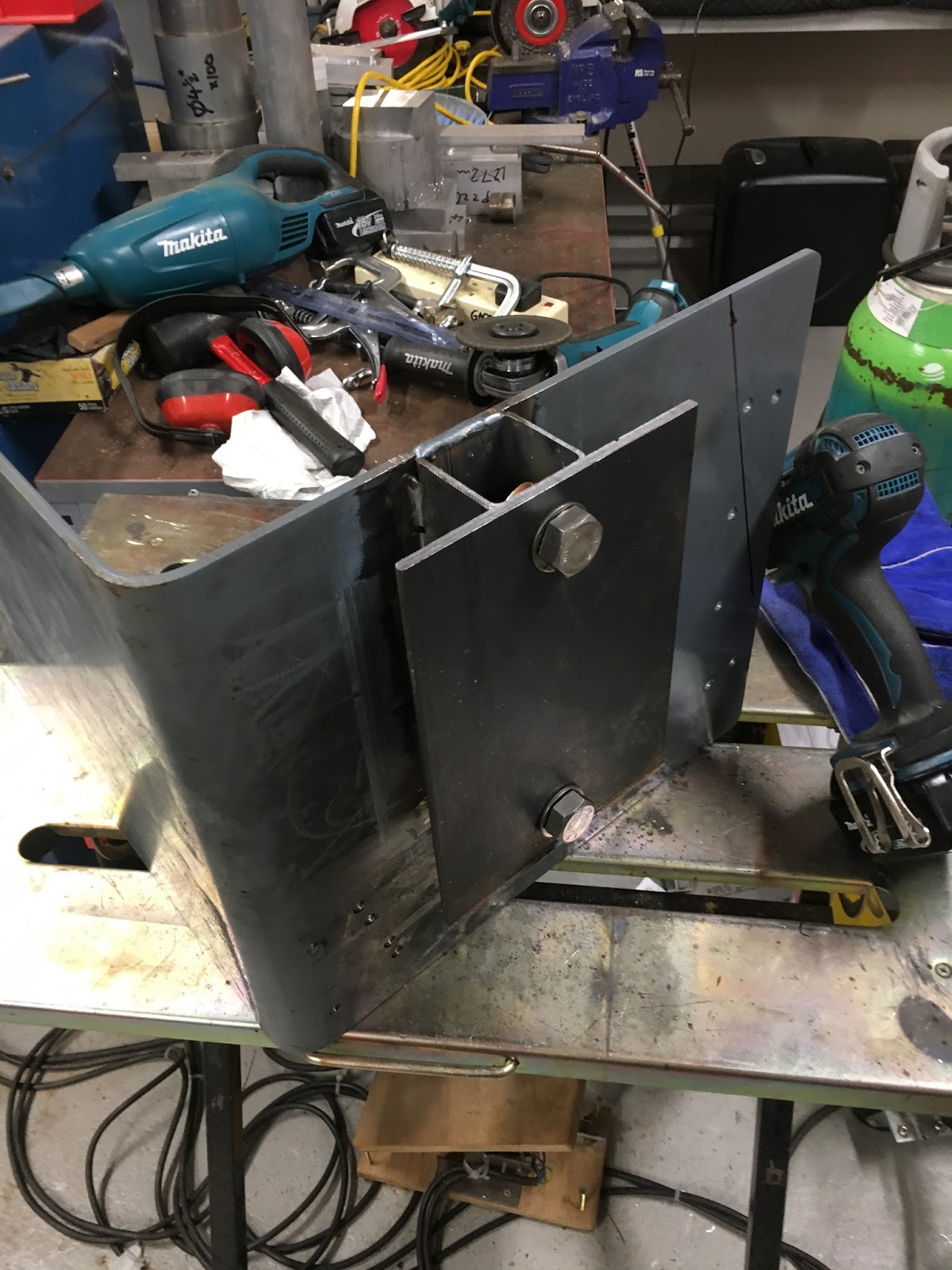
It's bloody heavy, being composed of a 10" rotary table, an adaptor plate, a 3-jaw chuck, a welded up bracket and a massive stepper motor. When reassembled, the table is driven by a toothed belt (missing) which is protected by a fabricated cover. This is the main lump (ie less the motor and cover):


 The belt tensioner is a couple of bearings on a swinging arm. That's better than a set of slotted holes to slide the motor in, in my books at any rate. A man after my own heart - it's how I've designed the drives for the Bridgeport CNC conversion.


As you can see, it's pretty hefty and I don't want to risk buggering my back again, so I used the lifting eye John had provided to lift it with my Weber engine crane :


There was a bit of backlash between the input (worm gear) and the table (worm wheel) and although it wasn't bad at all, this seemed like the time to adjust it the best I could. The only experience I have of RTs is through the Chinese Vertex clone I bought a few years back. On that design, the input worm is mounted on an eccentric body, so it's quick and easy to rotate that to adjust the backlash. On this one, there was clearly a different means of adjustment.

In fact, there's a funny long bracket / body that is held in place by 4 bolts. There's enough slop in those counterbored holes to allow some adjustment. What's not immediately obvious unless you look for it is the adjuster that pushes the worm gear assembly into the worm wheel. This is the funny worm gear bracket:


It's starting to clean up nicely, with WD40, green pot scrubbers and lots of kitchen paper:


If you look carefully, you can see the adjuster pillar that pushes the worm gear to adjust the backlash. You can adjust this using an Allen key inserted through a hole in the mounting foot:


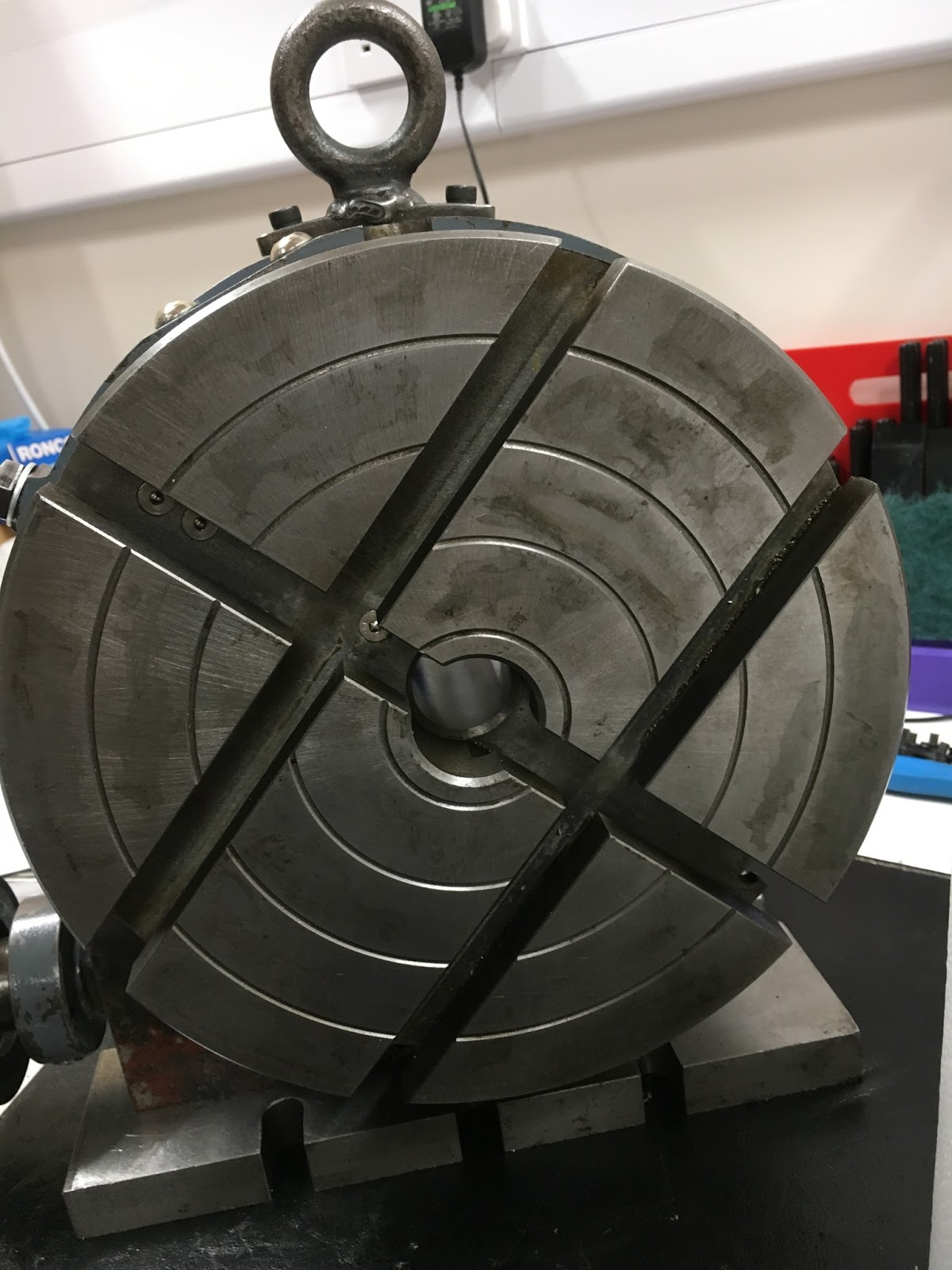
The worm wheel and table look to be in very good condition. It's obviously a good quality table and has had little use:


I'm pretty certain that John hacked off the bolt slots in the top of the table and ground them off. And at the base, it looks as if the piece of gauge plate substitutes for the original cast slots:


This is the worm gear and its funny bracket. No wear to speak of:


Here we are, all back together again:


I've fitted 3 bolts to fill the open holes. They were for the original lifting eye (2 x M8) and the table lock (M10). Job done - all greased up and reassembled!


Now for the ancient chuck. It's had a hard life:


Look at the state of that!


All cleaned up and degreased with WD40 and Gunk (washable degreaser): 


Partially reassembled and regreased:


Loosen up the grime on the stepper motor:


I already have some "L" series belts for the Bridgeport conversion. This confirms that the belt is an L sized pitch but it needs to be shorter than these:


I piece of Velcro-type cable tie material gives a pretty good estimate of the required belt size:


I've ordered a 20mm wide "L" pitch belt from Beltingonline, who I've used before. It's clear that the next standard size up from my estimate is 476mm length. I readjusted the green thing and it looks as if that should be fine. In old money it's a "187L", which I assume denotes that it is 18.7 inches. That's 50 teeth at 3/8" pitch which seems about right - it would be 18.75" to be exact.

Silicone sealant to fill the hole where there was probably once some form of gasket:


This is the original cover, engraved with John's handiwork:


And the 3-jaw chuck, reunited with the backplate. Still pretty well worn out but at least it's clean inside and out - and greased up.


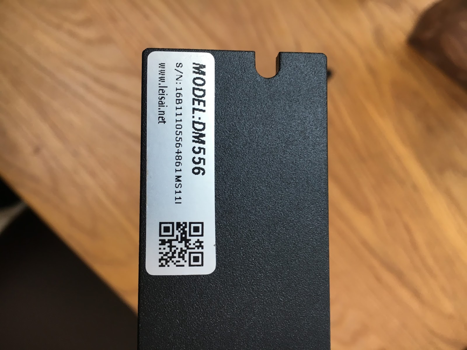
I've ordered a Leadshine DM556 (50V, 5.6A) stepper driver from China (£38). Whether or not it is a genuine one or a copy won't be clear until I get my hands on it, but I'm hoping it will be a good copy if it isn't pukka. Or good enough. A genuine one from Leadshine is about £80.


There.

Final assembly and test of the spindle nose adaptor - RESULT!!

After the recent distraction caused by the 3D scanner, resurrecting the 3D printer and buggering about with the throttle bodies for my Honda...