Retrofitting 1983 Shizuoka AN-SB CNC milling machine, Bridgeport mill, Colchester Bantam lathe and 1982 Tree UP-1000 CNC lathe with modern controls - and other workshop stuff
So let's see what we got here ie will the damned things go together? The CAD assembly was fairly convincing, enough for me to machine up all the parts. And most of those have fitted together reasonably well so far - for the cross slide (X axis) assembly mainly. The next assembly is the Z axis. I've made up most of the parts so let's have a go at assembling it.
The first challenge is figuring out the position of the fixing holes for the Z axis ballscrew brackets. I struggled a bit to figure out how to extract the vertical dimension for the M6 holes that hold the brackets to the bed. Then the penny dropped - you view the component from the front and then fit dimensions to that drawing.
Here we are. Both ends drilled and tapped. The biggest uncertainty was the horizontal distance. In the same way that I struggled to measure that up for the CAD work, I also struggle to measure it now. I've deliberately included about 1mm slop in each direction for the ballnut yoke but the lateral movement required is closer to 5mm.
I have some 1/4" cold rolled plate that is just what the doctor ordered. Got those manually squared up and drileld out on The Shiz.
And deburred
That did the trick. It seems to assemble without any fuckups. Pleasingly, the backlash is too small to measure on this Kurt branded Chinesium indicator.
The end stop is formed by the carriage hitting the ballscrew bracket, as planned. The other parts don't clash.
The glass encoder scale also fits - almost. The fixing holes in my brackets are about 2-3mm too far apart. I will fix these with a shim on the right hand (in this pic) bracket which does little apart from support the end of the scale.
And here's the cross slide (X axis) motor and bracket in place. Yes, it sticks out the back a bit but I always knew it would.
That will do for now. I'll now remove the motors and connect them up with the LinuxCNC controls. I may also need to start thinking about a control cabinet at some point soon.
The Z axis ballscrew is about 1m long, yet it needs to be around 800mm. Time for some surgery. That's a 1m steel ruler alongside it. Forgive the state of the desk - clearly time for one of my periodic blitzes.
Mark the position for the cut with some tape - and cover the ballnut and the rest of the ballscrew to keep grit at bay.
There. Angle grinder.
Mount in the lathe, with crappy packing pieces to prevent it whipping and becoming bent. I'm not about to remove the ballnut just for this operation.
Turned down and grooved to take a circlip. I don't have a narrow grooving tool, so am using a 3mm parting tool.
Sorted:
Fits inside the free (floating) bearing housing.
Now let's see about mounting it to the main body of the machine. Exactly where do the mounting holes need to go?
Background - 4th axis operation vs Fusion 360 changes:
David Loomes (Xoomspeed) has done some great work on his Tormach / Pathpilot system, particularly with in-process probing and his wireless probing system, that allows a touch probe to be used in an ATC system. He's done some great videos, sharing what he has been up to.
Not so long ago, I put the finishing touches to my own design of 4th axis, using a harmonic drive and a Yaskawa Sigma servo drive. At almost exactly the same time, Autodesk performed the full reverse ferret and announced the end of free access to Fusion. Or at least a significant hobbling of many of the functions in the free version. This didn't sit well with my Scottish-Yorkshire heritage, given the annual subscription cost. Furthermore, the details of what was in the free version and what was in the paid version was as clear as mud. I dismounted the 4th axis from The Shiz and left it to collect dust while the situation became clearer and I sulked about the new reality.
Tim Paterson has developed a pretty functional Python add-in for Fusion that allows the use of multiple tools and the replacement of rapids. These were the main annoyances that result in the free version. Have to say it worked fine, once we'd figured out the need to issue a G90 after each toolchange retract. However, he designed it to run all the toolpaths in the current file, whereas I often have multiple setups and machining operations within each component. He didn't seem keen to change that, and it made the outputs files rather difficult to work with - for one, they always ended up being single digit, sequential files (one per setup) and neither the post processor nor the finished file would be presented during the post operation. Not very user friendly, although it's perhaps churlish to criticise.
Finally, as 2021 dawned on us, I had recovered enough from my period of sulking and moaning to contemplate coughing up for the annual subscription. The NY offer of 30% off is about as good as it will get, most likely, so I thought bollocks - in for a penny, in for a pound (a day).
Almost a year ago, David posted a video of a 4th axis test piece he'd created for checking out his brand new Tormach "Microarc" 4th axis. This doesn't require the ruinously expensive "manufacturing extensions" to run, although it does require the paid version which allows for positional 4th axis moves.
I want to use my favourite 10mm long series end mill, rather than the 6mm and 8mm cutters he used.
I needed to extend the model's supporting "nose" to avoid the larger cutter gouging the stock towards the end due to lead-in and lead-out moves.
I finessed a few of the parameters to suit my machine and cutters.
This at least shows that the paid for version can implement positional (indexing) moves. So while I may not be able to generate true simultaneous (sort of "full 3D"?) toolpaths, there is still useful functionality to be had. It seemed like time to end the royal sulk and see what can be done with my 4th axis.
Here's the part in CAM - with my 4th axis used as a fixture. The jaws are the outside type here but that's a sort of worst case condition. I'll perhaps grab some inside jaws if I can be bothered some time....
Ready to go? I mounted and trammed my 4th axis, loaded up some 32mm loominum and braced myself for action.
Hold up, fatty!
Seems it's not as simple as that. Swissi recently released an update (v005) for his supey dupey post processor. Naturally, I installed that, as he needs people to test it out and find any issues.
Setting up the workpiece in Y:
....and Z
Air cutting the part. Not long into the program, the machine wants to drop the spindle to this position. Doesn't look right!
Here's what the tool and toolholder look like. That's a crash in anyone's book. WTF is going on?
Luckily, the Centroid s/w was clever enough to spot an issue, although this issue could easily have caused a problem that wouldn't have got picked up.
Turns out the v005 is generating an "E10" command instead of a "G54", on my machine at any rate. Knowing me, it's more likely I've configured something incorrectly, rather than Swissi messing up. Either way, v003 still works correctly, so v003 it is. The effect of the "E10" is to screw up the WCS - just what you need to break things. Nice.
Squeaky bum time:
So, having spotted and (hopefully) rectified that, at some point it becomes necessary to get on with the job. Which I did.
Result!
That came out well.
Perhaps I'd have got an even better surface finish if I'd upped the speeds and reduced the feeds on the finishing passes but I'm not about to repeat the whole process. Suffice to say, I'm very pleased with the end result, I didn't break anything or crap myself, I am getting a feel for what my 4th axis can do for me and I'm very grateful to David Loomes for inspiring me to stop sulking and test out my 4th axis.
Currently, the end of the encoder scale next to the "(axially) floating " bearing bracket is magically supported in thin air. I need to make up a bracket for that. It doesn't need to be massively strong.
The bearing bracket is fastened to the bed by 2 M6 screws. There are also some cross drillings that will be blocked off by those M6 fixings. However, there's a good 6.5mm of steel in those cross bores and they are 5.4mm diameter, so easy to tap out M6. That's more than enough to support the encoder body and although it won't be 100% threaded, it will be pretty strong. So I can hang my bracket off those and avoid having to make any more holes in the machine body.
So now to model up a bracket in the assembly:
That should work. Projecting the various holes onto the body from the other components ensures it should fit together out of the box. Like this:
Let's make the thing!
Chop off some 2"x3" stock
Faced off and ready to go
Top side done, now just need to face off the sacrificial base.
Sorted. Yesterday it was just a sketch and extrude component in Fusion. Now it exists.
Not many bits left to make now. Must be about time to start trial assembly...
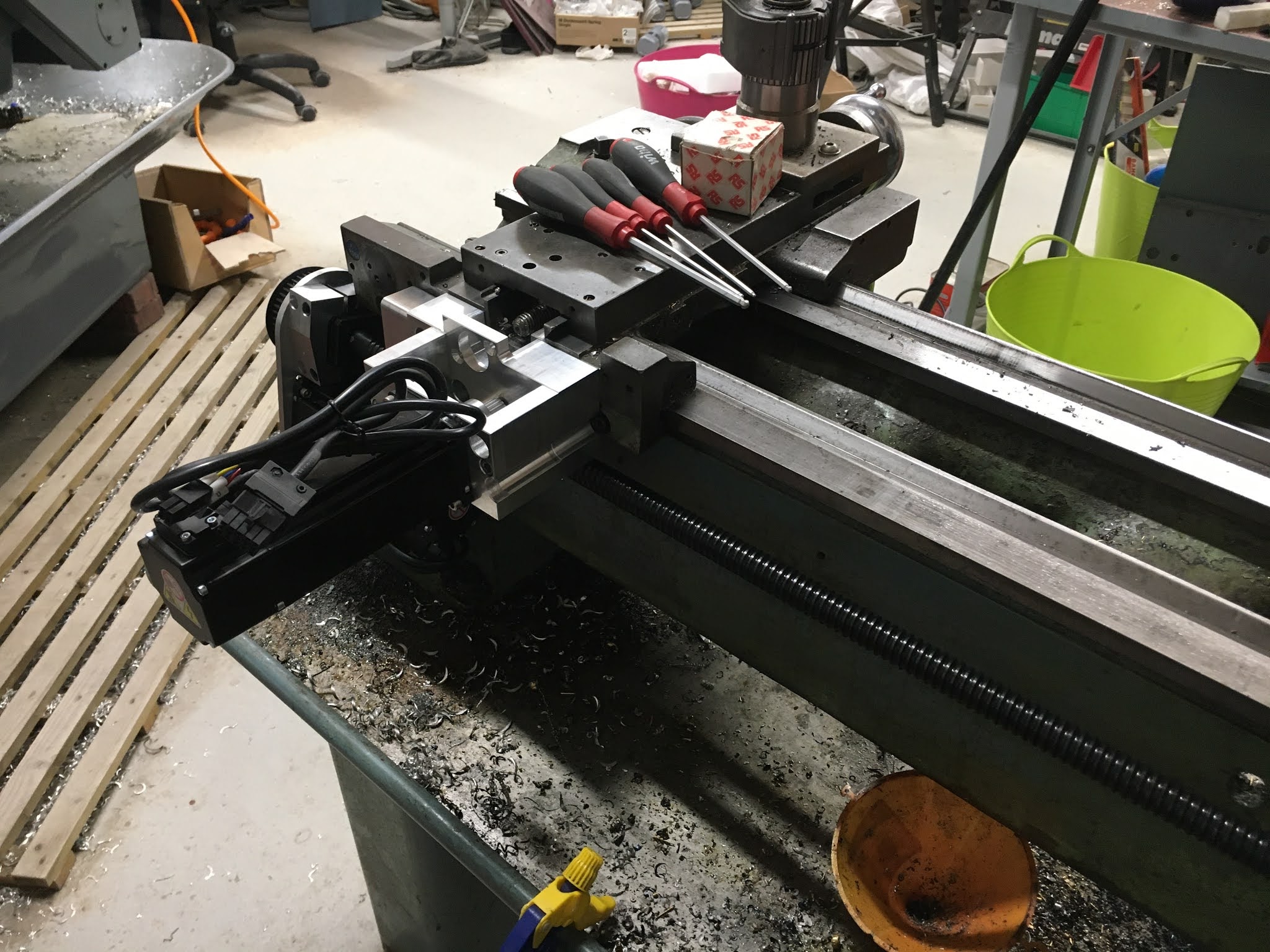
Here's the tailstock end of the machine, with the ballscrew, bearing bracket, encoder scale and motor in position. The motor / pulley centres are at the correct length for the belt and pulleys I have now received from Bearing Boys.
With the driven pulley in place:
And the bracket I finished making yesterday. This allows the encoder to be mounted on the back of the bearing bracket.
...and also the plate that will mount the motor and allows +/-5mm of adjustment for the belt tensioning
Here's the model of the plate being CAMed up:
...and the toolpath
2D Chamfer toolpath problem:
The 2D Chamfer operation within Fusion 360 is a fiddle until you understand it. But even then, it seems to have evolved in recent days. Either way, it refuses to create a continuous chamfer around the oval slot, no matter what I do. This same toolpath was happy to run most edges I selected until a few days ago. Fuck nose what is going on. However, it's possible to use the 2D Contour operation instead - if you select the "chamfer" tick box. Here's what I mean, with the same oval chain selected.
2D Chamfer:
2D Contour:
Fair enough - 2D Contour it is then.
Once I'd realised that the motor has a 50mm diameter register (rather than 45mm), I was able to finalise the model and get it machined.
Sorted.
Need to manually countersink the 2 fixings so they clear the back of the driven pulley. However, my 6mm chamfer won't manage it without a multistage operation, so it's far easier just to use a manual countersink tool.
Found a piece of stock that's almost exactly what is required. Again, the CNC gods have smiled on me. I'll drill and bore out the main opening on the lathe, as it's 44mm diameter. With my recent record of failing to clear swarf from end mills, it's probably best not to do this in The Shiz!
Set it up in the 4-jaw. Note the ground parallels to ensure the stock is square.
Remove the parallels and start drilling
Boring with CCGT06 boring bar
Skim the face to ensure I have a datum surface that's square to the bore
Check it fits the ballnut!!
Time to check the Renishaw probe is still set up accurately. Runout here could lead to offsets etc in the work when I pick up datum features.
Ready to go
2D Adaptive to rough out the externals (3D Adaptive would want to remachine the cavity)
After 2D Contour and 2D Chamfer to finish
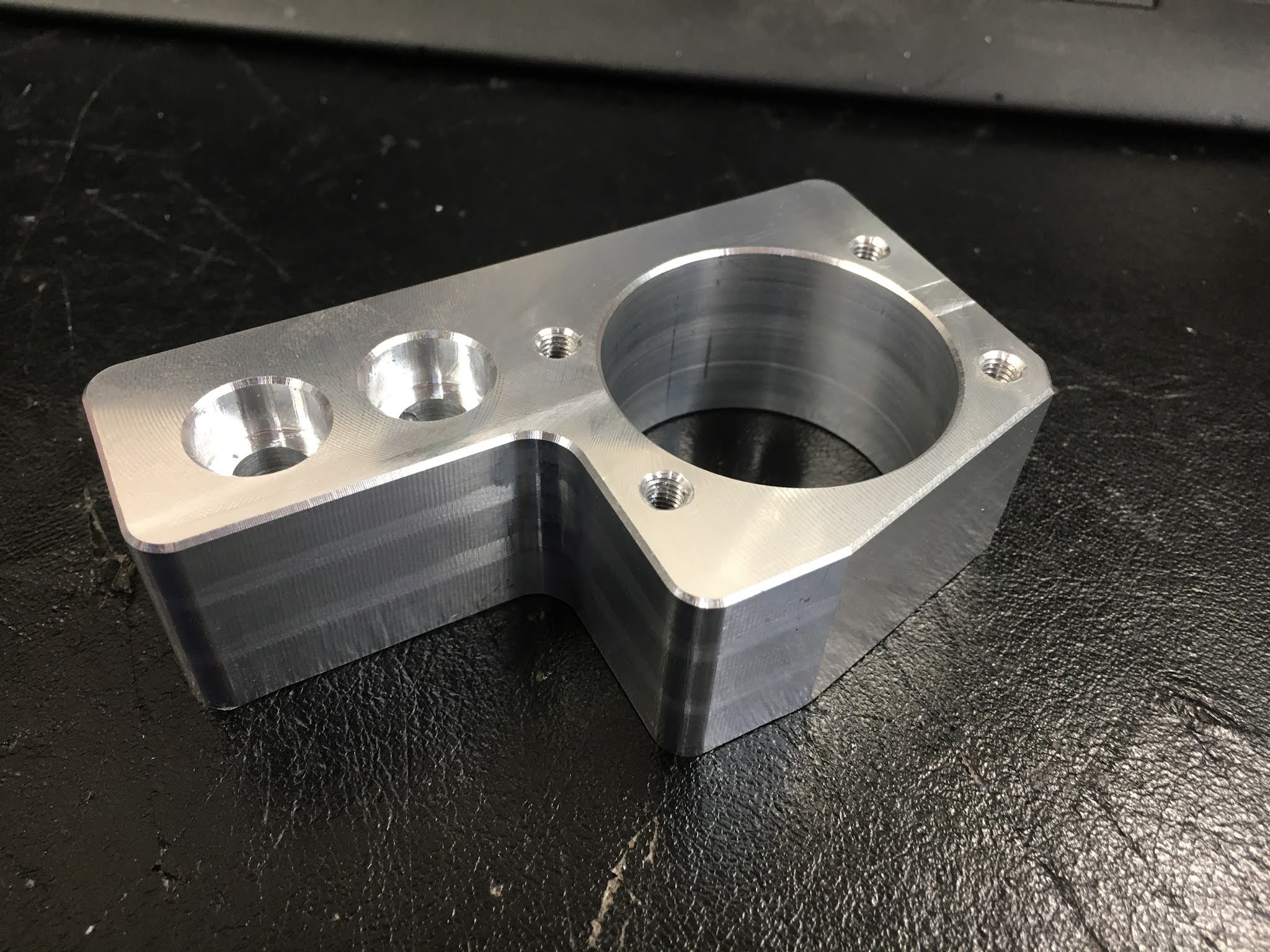
Looking good. Just needs flipping and the raft to be faced off - about 8mm thickness
There. Deburred and M5 holes tapped. Done.
I'll need to drill and tap the corresponding holes in the saddle bracket. Having modelled those in the assembly, that should be a simple job.
Let's think about fixing the ballscrew to the bed next....