Sunday 29 March 2020

Z axis bearing retainer plate machining

Behave, fatty!
It's all very well dreaming up all sorts of things to get started on. But first, how about finishing what you started? Before all this virus stuff hit us, I was part way through making the parts for my latest (final?) version of the the Bridgeport CNC conversion Z axis assembly. Thought it might be a good idea to finish this off before gadflying off onto something else.

Bearing retainer plate - what up?

It's what retains the ballscrew thrust bearing. A lozenge shaped piece of steel with 3 holes in it - one to clear the ballscrew and 2 for countersink machine screws. I like to keep things reasonably simple.


Best way to model this part is to create a projected sketch within the housing assembly and extrude it etc. That way it's linked to the housing in case I should ever decide to change the housing (it is parametric after all). Here it is. I created a 0.25mm offset around the circumference to ensure a degree of clearance so that it will stand a chance of fitting into the cavity. The precise location isn't entirely critical.

I also need to create a stock model for the piece of steel I found. Seems to be bright (cold) drawn steel of around 1/4" nominal thickness. Measures 6.35mm, so pretty close to nominal, then. 


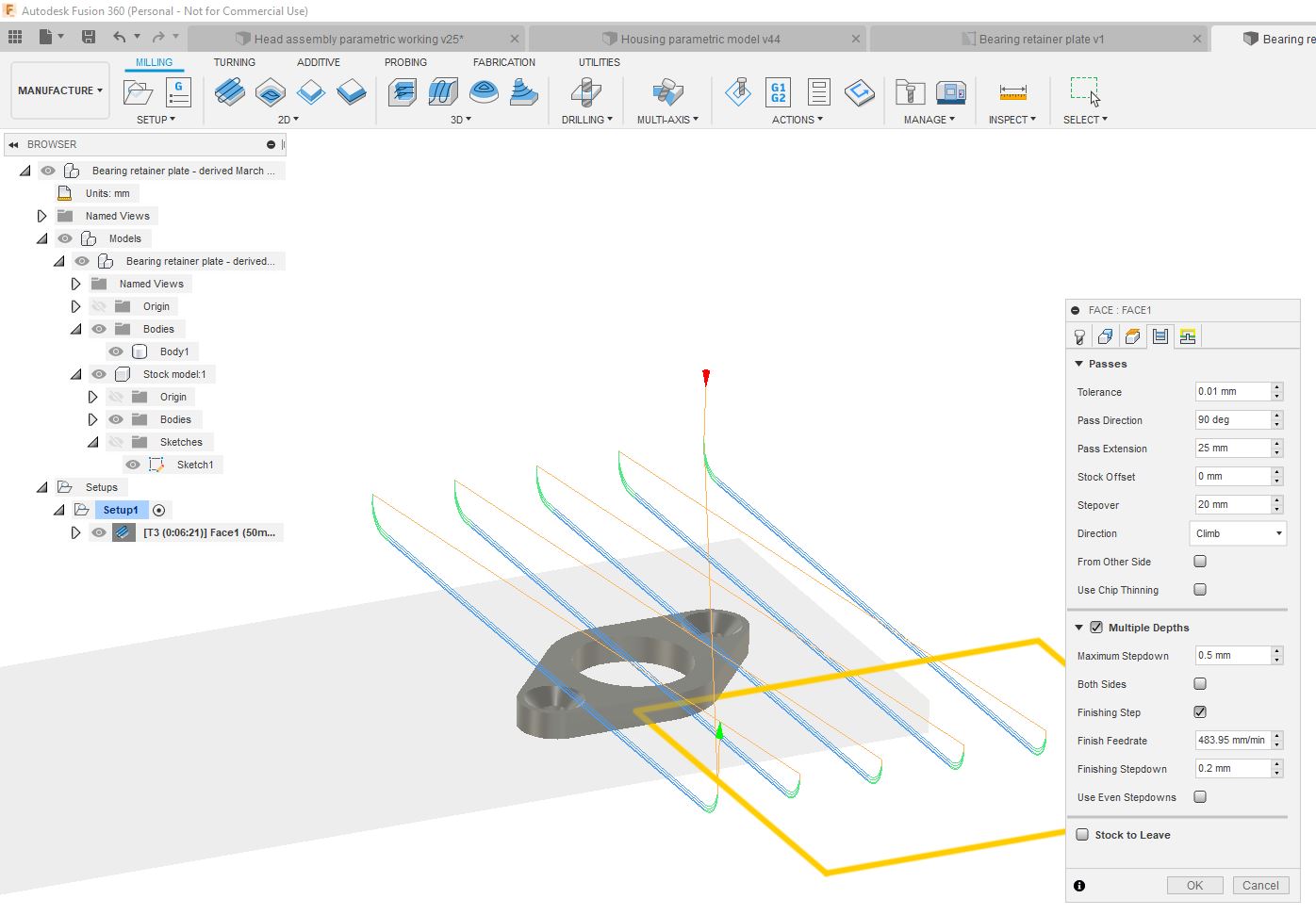
Here's the plate buried inside the stock:


It's easy to pick up the X, Y & Z positions at the corner shown using the Renishaw probe.


This is the CAM setup, showing the initial facing toolpath. Obviously I don't want to face off the entire length of the stock, so I'm cutting across the width of the stock and using climb mill only, to give a consistent surface finish. Furthermore, I thought it best to use only modest stepdowns this time, to avoid chatter and nasty patterns on the surface, as it's only 5mm thick after facing.


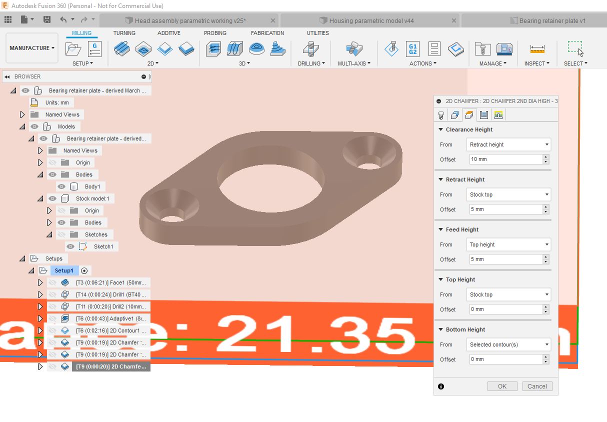
This was my first pass at the toolpaths. Looks ok to me, although the chamfer cutter is only 6mm diameter and the OD of the chamfer is 11mm, so there is only a tiny margin. It also means that the centre of the cutter has almost no surface speed. Not ideal. This sounds like an ideal opportunity to spend an hour or so buggering about with the 2D Chamfer settings....


Chamfering - again!

Hmm. Rather than try to machine the (large) chamfer in one pass, better perhaps to chamfer to a diameter of ~8mm, then dive down to the final depth and repeat the 8mm chamfer (forming a sort of counterbore), then finally chamfer the 11mm. The 3 operations should (ideally) result in the same outcome as if I'd used a single, large chamfer mill, but achieved using a smaller one in 3 moves. This is partly due to me being to lazy to swap over to the 3/4" chamfer mill, partly due it being not as good as the 6mm chamfer mills and partly due to me wanting to figure out the chamfer settings.


The way to prevent a full depth chamfer is to limit the bottom depth - to 1.5mm here. So it only creates a shallow chamfer.


Then repeat the exact same operation without the 1.5mm vertical offset. This results in a narrow bore with a countersink at the base:


Then finally, go full diameter at the full depth - this takes it out to the final 11mm diameter.


Here's the combined operation. The 3 blue traces show the paths of the tip of the tool. The first operation is the small circle at the top, then the small circle at the bottom, then finally the large circle.


And the bottom line is that it works. You can't tell that it wasn't done in one pass.

Machining:
Anyway, action talks, bullshit walks. So here we go:


Turned out good.


Bandsawed the tabs and belt sanded them down. Happy with that. 


And above all, the bugger actually fits, which is the bottom line.


The Stupid Fat Bloke at large - again

And here's the one that got away. This is an 8mm carbide tool I used for some "experimental" feeds and speeds last time I cut some steel. I recall being pretty impressed that it had (almost) survived the experience, although closer inspection showed a couple of the teeth were chipped. No matter. This was running at the full fat 6000rpm, with 0.033mm/tooth, which translates to 800mm/min feedrate. Obviously this was dry too. 

I just reused the tool - settings and all. It made a pretty impressive (heroic) job of the central bore which I'd predrilled, then set into the 2D Contour. I like tools that glow yellow hot but it clearly wasn't going to end well, so I stopped the operation and swapped tools before the workpiece got damaged. The bugger is that I thought I was videoing it - but it turns out The Stupid Fat Bloke had taken over video duties and had some how fucked it up.


All I have to show for the excitement is the (uncoated) tool with bits of steel welded to it. It survived largely intact but will be put out to grass now.


What next?
Let's assemble what I've created so far. I should have enough parts to get it to the point where it actually operates

Retractable cross slide for the Bantam?

Really?
There's only so much moping about you can do before you need to get a grip and start doing something constructive. So, now that I've got my work situation sorted for now, I need to give some thought to getting my hands dirty again. One upside of this working from home lark is that I am not having to work away from home during the week so I now have my evenings (and more of the weekend) for workshop time - not something I was anticipating any time soon, as we weren't expecting to be moving house for some months. Notwithstanding the need to keep the Domestic Manager happy by doing some work on the bathroom refit, that boils down to cutting metal in some form or another.

Not being one to finish one job if there is the possibility of starting another, my mind has been flitting about trying to identify something to get stuck into. I think I'm probably going to try to stay focused on the Bridgeport conversion Z axis assembly in the end but if I'm feeling like getting stuck into something more traditional and manual such as a bit of lathe and mill work, there are some options I've had on the back burner for a while.

High speed threading:
Just before I got the CNC conversion bug in Canada, I was putting the finishing touches to a threading clutch system for the Bantam. This is similar to the system fitted to Hardinge HLV lathe and others. Because the clutch is running at spindle speed, you don't need to worry about closing any half nuts at the wrong position and screwing up your partially cut threads. This is particularly relevant when cutting metric threads on an imperial machine, for instance. I guess an exception might be if you are cutting a multi start thread but we don't need to be worrying about that any time soon.

My system is pretty much complete but for the fact that it became evident that some clot (no, not The Stupid Fat Bloke) had clearly crashed the gear train and bent the output shaft from the headstock gearbox - the one that drives the start of the change gears. Presumably they had had the sense to replace the sacrificial shear pin with something more solid. This was an ex-school machine from what little I know of it. Bottom line is that said shaft has a fine wobble on it, despite my best efforts to straighten it. I've not managed to find a replacement so far. Anyway, that seems sufficient excuse not to actually fit the thing to my machine. 

Retracting cross slide:
Once you've finally got yourself one of these high speed threading clutches installed, you'll find yourself wanting to withdraw the tool from the thread while returning the saddle to the start of the thread, before dialing it back in for the next cutting pass. That's where the retracting cross slide comes in. These are usually use an an eccentric to cause the cross slide to withdraw 5-10mm, then return, by means of flicking a small knob in and out (fnaaaarrr). 

Here are some examples:
https://www.hobby-machinist.com/threads/tools-to-simplify-threading.20867/

http://www.primrose-engineering.co.uk/raglan-retracting-cross-slide/ 

Of course, while the principle is reasonably simple, the implementation on a particular machine requires careful thought, as the space is often rather limited. So here's what the saddle / cross slide setup looks like on my machine. There's quite a lot going on here, which limits the room. Certainly, with the cross slide in its fully retracted position, it pretty much touches the micrometer dial. This brings any thoughts of fitting an operating knob on the top (where the oil nipple is in this photo) to a halt.


Whipping the micrometer dial off:


Removing the two hex socket bolts releases the leadscrew. The leadscrew is splined to the hollow splined shaft that runs in the housing I'm holding here. The pinion is drive by the apron and provides the power cross feed when engaged.


You can see the driving pinion if you peer through the hole in the apron:


In the exploded view below, the worm wheel #27 is driven by the long shaft along the front of the machine. This drives worm gear #14, which also incorporates a std pinion gear that is in constant mesh with gear #10.

The cross slide power feed is engaged by pulling the selector knob (#12) towards the operator. This brings gear #10 into mesh with the pinion on the cross slide leadscrew. To engage the longitudinal feed, the knob is pressed in, away from the operator so that gear #10 meshes with gear #9 instead - this drives the pinion that meshes with the rack on the bed.


This cutaway shows how the cross slide leadscrew and the drive pinion are assembled:


An exploded view of the saddle assembly gives a different perspective:


I forget who gave me this but these photos show what you find if you get into the saddle. This is the power feed selector knob with its sliding gear (#10) 


Here the selector knob is fully pushed in so that the feed is connected to the longitudinal rack and pinion. Or would be if it were mounted on the machine.


This is the overload knock-off mechanism that automatically disconnects the power feed when the saddle or cross slide hits a stop. It results in an increased axial force on worm wheel (#27) which eventually overcomes the detent stop (spring loaded pin) and causes the straight cut pinion to disengage from its meshing gear (not shown here). Simple but apparently quite consistent and safe.


Design concepts for the Bantam?
Space is tight, with the power feed selector knob, thread indicator dial (#16, telling you when to close the half nut) and hand wheel crowding for space. And that's no forgetting that the cross slide covers the handwheel "keep" (#19, extension nose thingy) when the cross slide is fully retracted. This is looking challenging...

Let's think on't before getting into this....

Tuesday 24 March 2020

CV brushup

Que?
No mate, not the curriculum vitae. I need to find somewhere to set up a work station so I can work from home due to the CV Thing. As we have 2 students living with us (offsprings Ewan and Tom), there's a bit of competition for the desk space we already have in the house. Besides, there's a handy space out the back, complete with double glazing, central heating, plentiful lighting and even a desk....

Trouble is, the place has become a bit of tip of late, not helped by me working away from home during the week (= no workshop time).

Here's a quick scan around the workshop. It's not pretty. Swarf everywhere, crap all over the floor. Tools left out. Desk covered in "stuff". Anyone can see that The Stupid Fat Bloke has been busy during my absence. I should really try to keep the guy out of my workshop if he can't learn to behave himself and take the piss when I'm away.


There's a desk hidden somewhere under that lot...


...if you look closely


Even The Shiz is in a state. And a lot of the swarf ended up on the floor.


It's as if a bomb had gone off.


Several hours and a lot of loud music later, we have this. That's a bit more like it!


One upside of this home working business is that I will be able to spend some time in the workshop in the evenings. Wow, I thought that would be months away, once we'd finally moved house.

Merry

Final assembly and test of the spindle nose adaptor - RESULT!!

After the recent distraction caused by the 3D scanner, resurrecting the 3D printer and buggering about with the throttle bodies for my Honda...