Retrofitting 1983 Shizuoka AN-SB CNC milling machine, Bridgeport mill, Colchester Bantam lathe and 1982 Tree UP-1000 CNC lathe with modern controls - and other workshop stuff
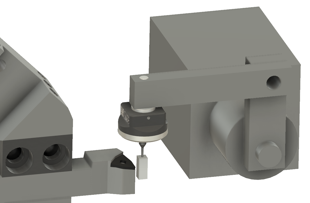
Here's what I used last time, to investigate how the Centroid touch off features worked. Perhaps there is some intermediate scheme that I can use to mount the probe. Removing the upright from this mag base looks like a good starting point:
Mounting it in a tailstock chuck, then adjusting the probe position looks like a promising approach. Something like this:
Firstly, I need to remove the ball end from the probe tip, as the lump of Bluetack isn't entirely appropriate for the job. Presumably it's a 2mm ball bearing brazed(?) to the end of the probe shaft.
Indeed. It held up well against the angle grinder - until it didn't. The ball itself was as hard as witches' tits until it flew off into the dust and dirt on the floor. Job done either way. This leaves a simple 1.5mm shaft:
I can't find the key (square) stock I know I have somewhere, so finally I gave up looking and went with this 3/8" brass stock. It's a bit larger than I'd planned but I can always replace it later. Meanwhile, I was too impatient to machine it down and instead settled for squaring it off...
...and drilling a 1.5mm hole in the centre.
Yes, I only possess one drill in this size. Don't mess up, Fatty - you only get one chance.
Fits nicely, drill didn't break and a bit of Loctite is ideal for bonding it to the shaft. If I want to replace it, I can simply heat it up with the blowlamp.
And here we are. Yes, the large brass lump looks a bit silly but so what - it will do the business.
Good, so let's give it a whirl. With parameters #281 & #282 set to 9.525mm (aka 3/8") and the "safety clearance" distance reduced to 5mm, we should be good to go.
Here's what I get when I run the Z and X touchoff 3 times (telling it the tool number has changed between events). The offsets seem to vary by ~6um or so. This may be a best case result of course but at least it isn't instantly disappointing.
Let's mount a few different tools in the turret. Then I can touch them off and see what happens when I change tools with the turret and tell the machine to go to the same position in X and Z.
I will need to issue G43 after each tool change presumably, as indexing the tool doesn't in itself activate the appropriate offset. That's something else to familiarise myself with.
Here we go: It's early days yet but it seems you don't need a G43 for the lathe, just T0202 etc, to load tool #2 and apply offset #2.
I've now touched off in Z & X (it does them in that order) for the first 4 tools:
VCGT160404 LH turning tool
MGMN200 2mm turning / grooving tool
CNMG120402 LH turning tool
WNMG080404 LH turning tool
I then set X0Z0 with the DTI reading 2.00mm. Moving to X30 (to clear the moving tools!), then indexing the turret and setting T0202 etc then asking for X0Z0 resulted in the X and Z offsets being correctly applied and the tool tip moving to the intended X0Z0 position.
Using the Mitutoyo DTI (10um per div), I see tools #2-#4 achieving the same X position, with tool #1 consistently ~50um off. I'm guessing I didn't touch off as accurately for this tool. However, I seem to have sussed out the process and we appear to have a reasonably consistent result.
In practice, the tool change will need to be made with a G28 (tool retract) move, to avoid liquidising the probe, workpiece etc. But for now, I'm testing it out with MDI commands.
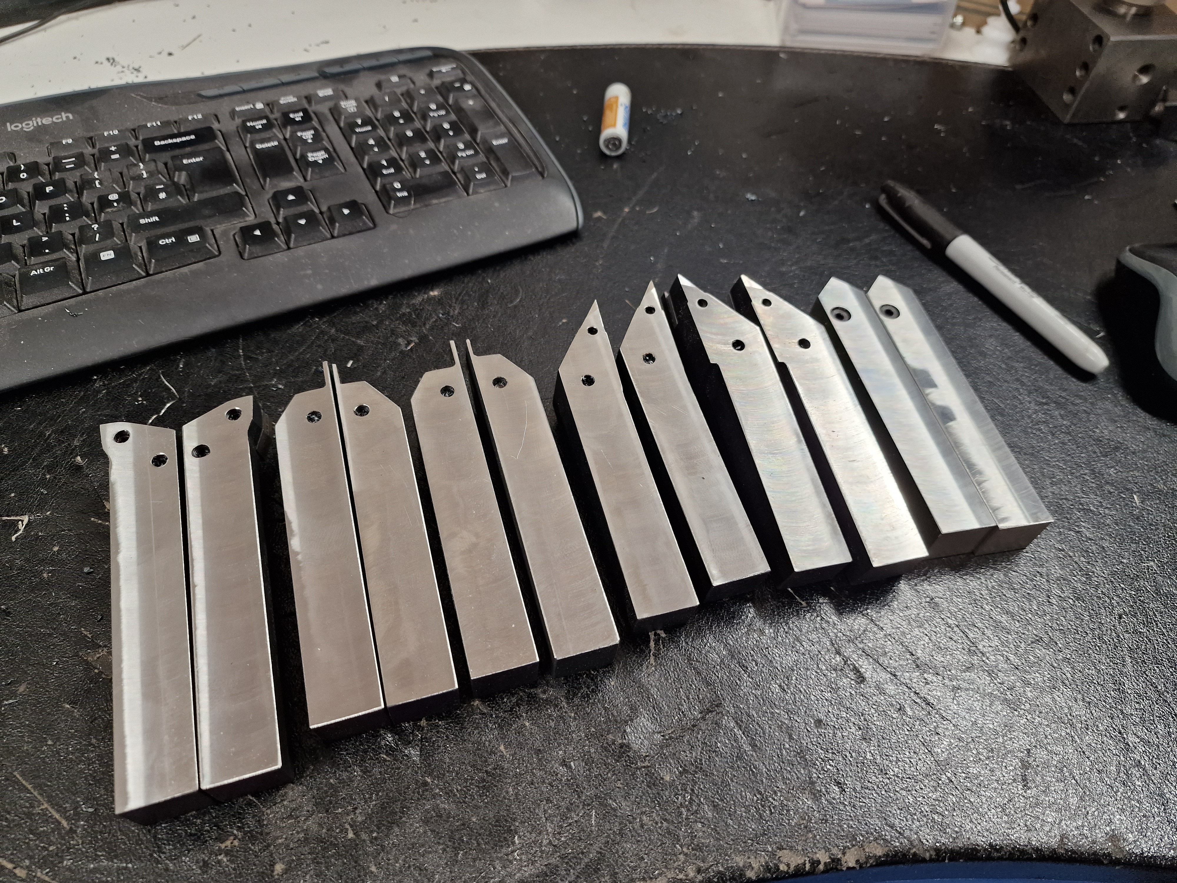
Now that I've bought a dozen toolholders from AliExpress, I have the task of machining them down to the required height for the Tree lathe. These are all 20mm x 20mm x 125mm sized, yet the Tree turret is designed for 3/4" (19.05mm) tooling, as it originated in the US in the 1980s. Not much demand for imperial tooling these days but the difference is only ~1mm, so I will skim them down on The Shiz.
Quick test with the hardness tester suggests they are generally hardened to something like 40-45HRC. So carbide inserts it is.
CAM setup: It would be entirely possible to use Centroid conversational programming to set the machine up for this but it's simple enough to do it in Fusion and I'm more familiar with this process currently.
There's only one tool (BAP300 50mm face mill) involved, so I simply need to probe the corner of the stock and check the tool length offset (Tool #25) is still correct, then off I go. 2500rpm and 0.06mm per tooth, with step down of 0.2mm. So that requires 5 passes and just under 2 minutes. This isn't good for the inserts (hardened steel, interrupted cuts etc), so no need to push it any further and I will need to deburr the parts, which will keep me busy while the next part is being machined.
Machine setup:
Firstly, before I start, how flat is the vise / parallel setup? The Renishaw probe isn't much use here, as it only indicates a threshold. The Mahr 3D DTI gives a visual (analogue?) indication.
Answer - pretty good.
How close to the alleged 20mm are these Chinesium things? Pretty reasonable.
So, off we go:
Here's the first example. Not a bad finish but the inserts are all new of course.
Measuring pretty close to the required 3/4":
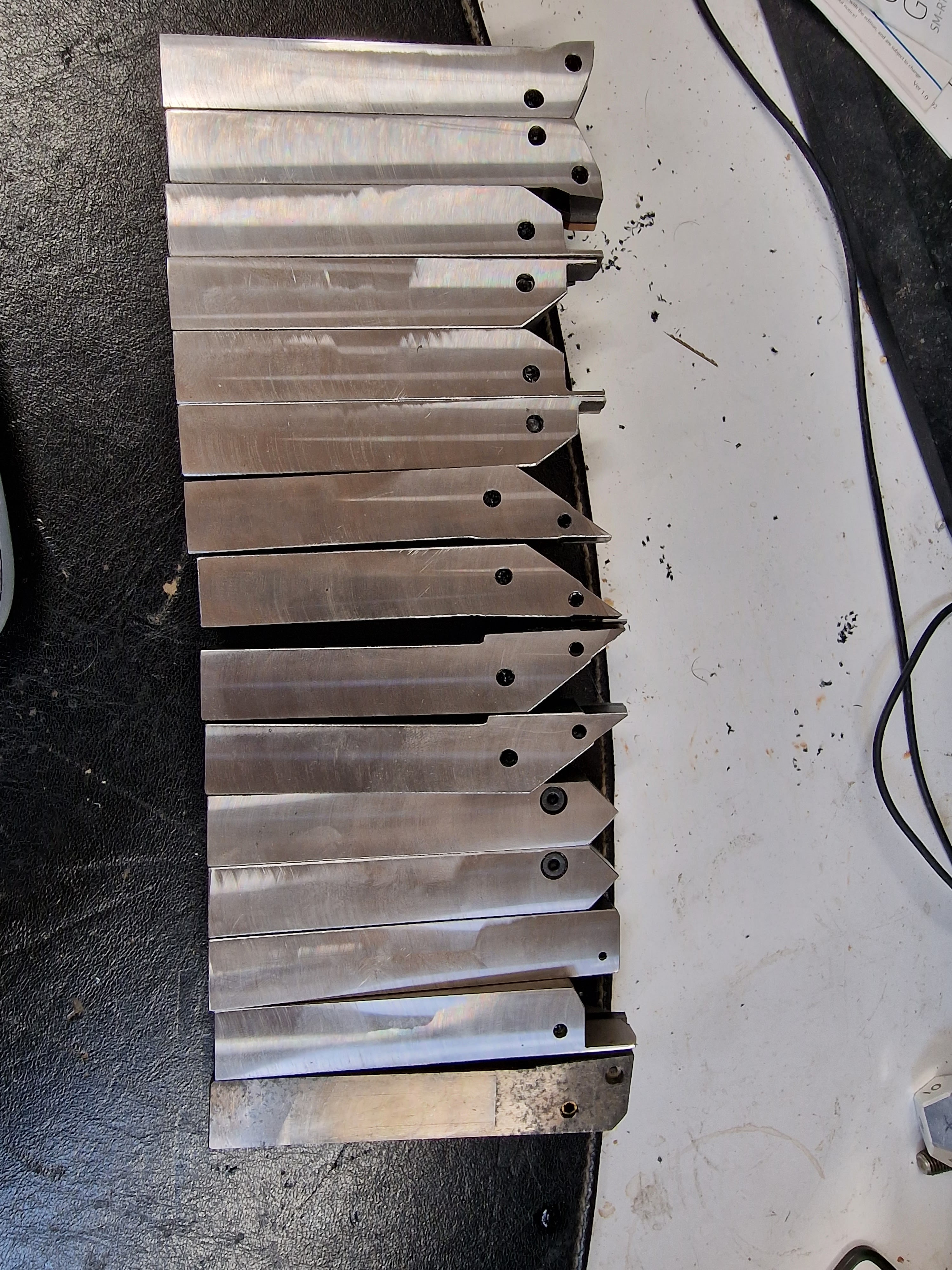
So off we go again. I have 12 of these AliExpress specials plus another couple of existing tools to do....
Getting there. I deburred as we went. The inserts were clearly suffering, as I found they became hotter as I progressed through them. I was machining them dry to keep the mess down and not thermally shock the inserts so I ended up wearing gloves.
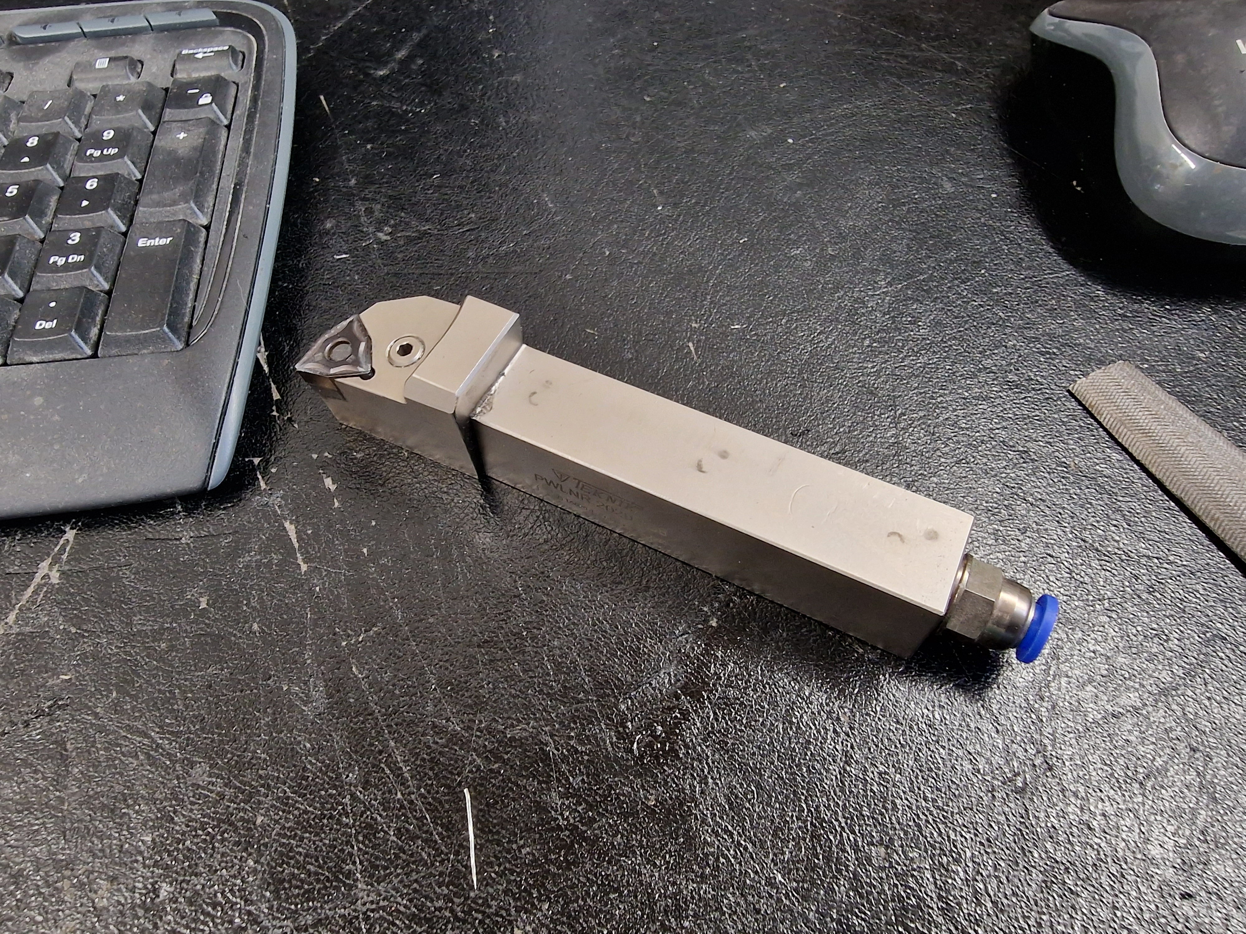
This Teknik trigon holder from Cutwel has through coolant, which complicates matters. As I have a couple of trigon holders already machined, I'll leave this one for now. Apart from the various plugs that would get in the way, the coolant coupling would foul the turret on the Tree, so it's questionable I'd be able to use it there anyway.
How was it, Fatty?
Bottoms up:
Right way up:
Good. That wasn't too bad and I didn't start any fires in the workshop.
Any damage?
Sure enough, 4 out of 5 of the inserts are chipped. Seems a reasonable price to pay for the work, not least as these are genuine Mitsubishi parts from AliExpress that didn't cost an arm and 10 legs. Here's one of them:
Good. Now let's think about setting up the tool touchoff system on the Tree. For now I think I'll simply mount the DIYO probe in the tailstock rather than dick about making up a pukka assembly. I've not been able to make a lot of progress recently for various reasons, so I'll cut a few corners for the time being in order to see some swarf sooner than later.
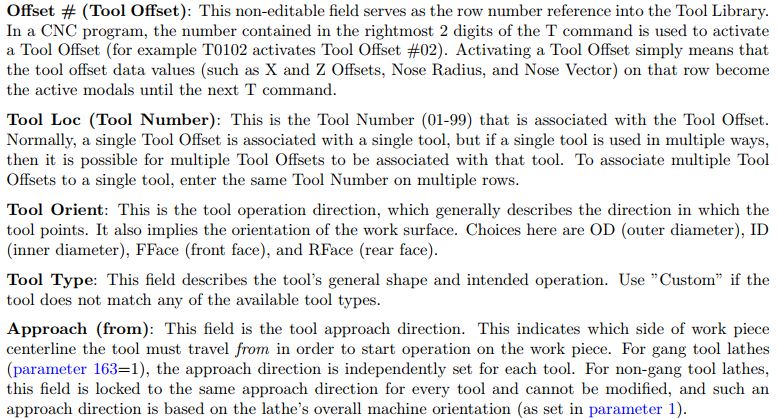
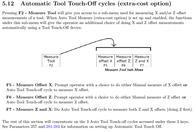
Setting up auto tool touch-off parameters in CNC12 Lathe:
With the "Pro" lathe licence, the tool probing is included although Swissi hasn't created a special "probe app" for the lathe (yet?). The setup is pretty simple and is easiest taken care of by the wizard. There aren't many things to set up. Once you have told CNC12 which input is the Probe Detect signal, the only parameters you can / need to set up are the stylus widths in X and Z and the "safety clearance" distance. That's only 3 parameters:
In my case, I plan to have a 6mm x 6mm square probe tip, so #281 ans #282 will be 6.0. I set the clearance to 10mm but that seems rather girly, so I may reduce that in the near future.
Running auto touch-off:
Fairly simple when you know how:
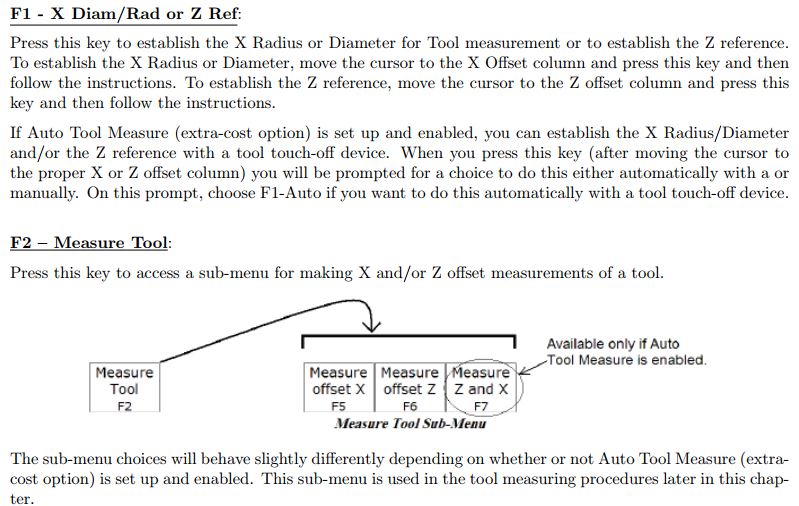
For touching off in X:
For touching off in Z:
For touch-off in both Z and X:
Uwe Mattern posted a YT video recently showing his setup with the DIYO probe and Acorn (Acorn 6 in his case, FWIW):
Mine pretty much does the same although I can't mount my probe on the spindle axis due to the constraints of the axis movements.
I have a spare input on Acorn, so got this set up and did some playing, using a bit of Bluetack on the probe tip ('cos it isn't designed for tool touchoff).
No video? It didn't happen!
Here's the most commonplace touchoff move ie a RH external tool. I know, I know - in my case, technically it's actually going to be a LH tool but let's keep life simple.
By flipping the "nose vector", I can change the probe direction in Z. This is what I'd do to change from a LH to a RH tool:
There. This gives me the confidence to know that my slightly unconventional machine setup should work fine with the Acorn software.
I need to be able to probe both internal and external tools, both left hand and right hand. Most of the probes use the "trilobe" concept, where the probe tip sits on the end of a sort of tripod scheme, with the 3 legs held against electrical contacts by a spring. It's what I have on the Renishaw MP1S and TSR27 probes used on The Shiz to good effect. This principle works fine for mill probing which only occur in 5 axis (+/- Z, +/-Y and -Z directions) but if you try to "pull" the tip away from the probe body in the Z direction, bad things would happen.
In an idle moment (couple of hours), I modelled the DIYO probe in Fusion 360 and uploaded it onto Grabcad. Looks good but the purpose was to be able to use it to design an assembly, taking into account the rather limited movement available on the key components that make up the cross slide, turret, tailstock etc.
In simple terms, the external toolholder and the internal (boring bar etc) toolholders don't present their tips at quite the same radial position. True, most of the external toolholders have a well defined length (125mm from the back the tool holder to the tip) and height (0.75" from the base of the toolholder to the cutting tip) but the radial position of the boring bar tip will depend on the diameter of the boring bar and the length of the tip.
The centre line of the boring bar holder is already defined by the boring bar holder block and is about 25mm further from the turret axis than the external toolholder tip - and the larger boring bars may have a tip-to-centreline distance of as much as 17mm or so. That gives a range of tip positions of getting on for 50mm and by the time you add some distances for actual probing moves plus the thickness of the probe head itself, I'm seeing that I will need to lose a lot of the available cross slide (X axis) movement.
Putting it another way, the position of the probe tip will have to be calculated fairly carefully to ensure it can probe the variety of tools I expect to use.
NB: On this machine, the probing move needs to be in different directions for the internal and external tools. The cross slide can only move away from the centre line (away from the operator), which means that the boring bars will be presented "upside down" with the spindle rotating clockwise. In contrast, the external tooling has to be "left handed", presented "right way up", with the spindle rotating counter clockwise.
This probe assembly is going to be hazardously close to the hydraulically powered turret, so a turret indexing move could easily destroy it. So my cunning plan is to mount the probe on a swing arm, with the tip pointing down. That way, if the turret indexes when the probe is in position, it stands a chance of pushing the probe out of the way rather than trashing it.
Obvs the first thing to do was to model up the key elements. The cross slide sliding limits are set to restrain the turret movement to its actual values - 245mm maximum centre distance (at X axis home position). The tailstock can also move along the Z axis and the upper swing arm is able to pivot down and out of the way. The construction details for the swing arm are to be determined but the dimensions and operating principle should be reasonably clear
Here's my solution.
With the boring bar fitted, there is still a modest clearance between the boring bar block and the tailstock. I suspect I may want to fit a limit switch to prevent them clashing, as the cross slide is able to move the tool tip slightly beyond the headstock / tailstock axis:
With the external tool fitted, the cross slide is slightly further away from the tailstock but still has some movement left between this position and the home position. The probing move is in the opposite direction, clearly. I believe the Centroid CNC12 is clever enough to cater for this, using the info in the tool table - assuming you have correctly populated it that is.....
This looks workable, although I may be advised to test out the probing moves before getting too far into the build. The "build" itself is actually fairly simple, comprising little more than the swing arm assembly, now that I have done the calculations and figured out a scheme that appears to actually work.