Thursday 17 August 2023

Chip time - let's do it - 16mm Autolock collet to JT1 taper

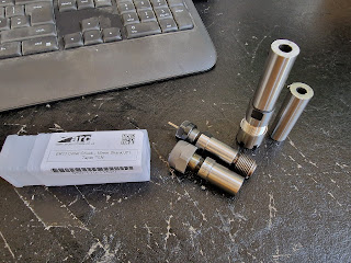
These are the tools I'll need - roughing / finishing tool and threading.


Firstly, set up the stock. This is 20mm EN8.


Just checking - what is the max dia of the centre drilling? The pip looks like 1/4" diameter, so I need to make certain I don't make it bigger than this. It's responsible for the radial position of the rear of the collet chuck, so the drilling needs to be a good fit on the pip. 


Here's the rather shitty looking live centre that came with the Tree. Some rust but mostly just grease and muck. Got a cleanup in the Bantam, along with various other MT3 chucks and centres.


I don't have a chuck for the turret yet, so the 8mm centre drill will have to go in a boring bar holder.


But hold on - the drill isn't on centre height. It's about 0.5mm above. You can see the path of the drill tip in the inked up area. Not good.


Removed the locating dowels for the drill / boring bar block and was able to "adjust" the height. That's a bit of a bodge but i don't see any better fix in the circumstances. Bottom line - I managed to centre drill the stock without snapping the carbide centre drill. Unlike HSS they don't flex and the pilot drill is very fragile. You are looking at ~£20 worth of drill here.


Quick facing off and chamfer...

...and off we go.

Looks reasonable.


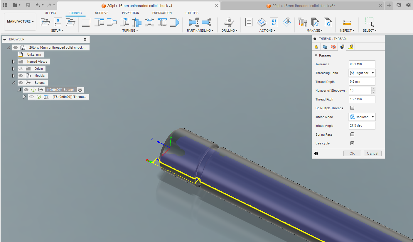
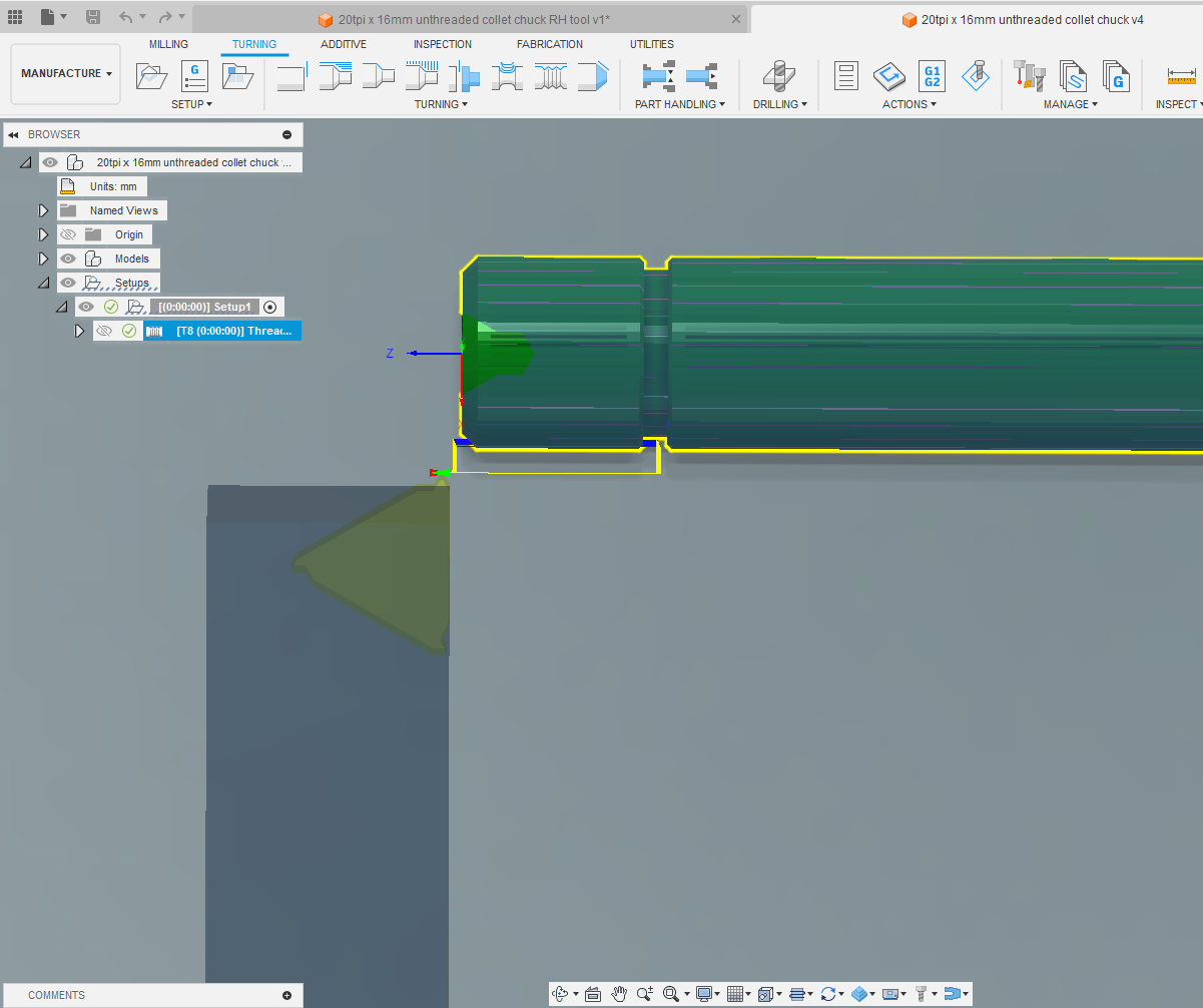
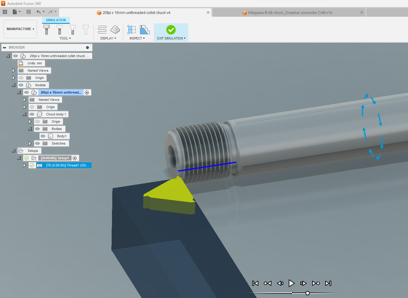
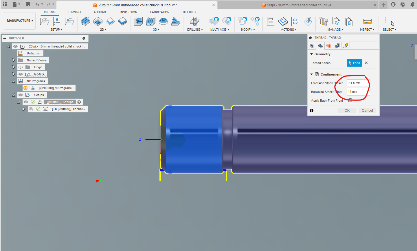
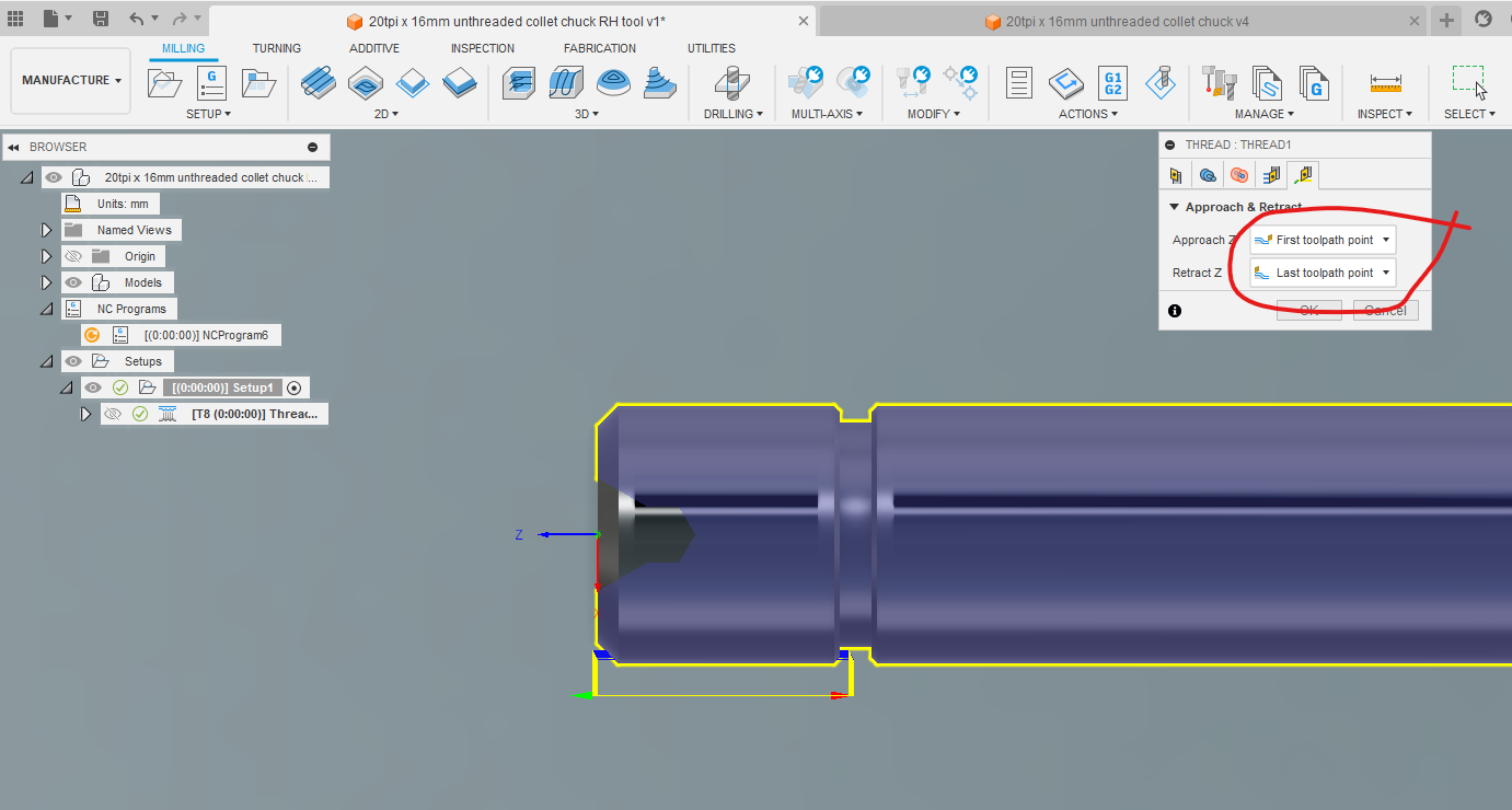
Now for the 20tpi thread. Is it really 16mm x 20tpi?


Seems not. Looks more like 5/8" x 20tpi which sounds reasonable. So a "metric" Autolock collet has a metric (eg 16mm) bore with an imperial thread - that sounds much more credible. Cut the tread 150um deeper by adding -ve 150um of tool wear compensation (should be a nominal 125um difference, which would take it from 16mm to 5/8") and found Nirvana.


Then parted it off. The surface finish isn't perfect but this is EN8 and I was using a general purpose tip at low speed (2000rpm).


It's a fairly convincing result, either way.


So - now I know what is required, I have adjusted the CAD model so we have 5/8" x 20tpi thread (15.875mm OD instead of 16mm) and a shorter threaded portion. Also removed the tool wear compensation, as the thread should be correct now.

So let's set up the stock again and make the part from start to finish....

Wednesday 16 August 2023

Problemette with ER16 boring bar concept

I thought I had a neat solution for replacing the ER11 collet chuck adaptor. But there is a slight issue with this cunning stunt. As you can see, the main body has a through bore of about 8mm. That is somewhat larger than the 60 degree centre pip in the Autolock chuck which is responsible for the accurate radial location of the inboard end of the cutter / collet chuck. So the only way around this would be to create yet another adaptor that would sit in the end of that bore, with a centre hole for location. 

This would be getting rather messy. Not only would I need to bore out that hole (to ensure it is concentric) but I'd also need to make up a mating part with a centre hole. All of those features would have their own tolerances which would stack up in the final assembly. I'm needing something better than 10um total runout at a guess, so this concept doesn't sound as if it would be worth all the buggerage.

Bingo!

At this point, I chanced upon a familiar looking component on the Arc Euro website. This is the exact same ER11 collet chuck adaptor that came with the speeder in the first place. 

The only obvious difference is the rather large / clunky nut. Obvs the only sensible thing to do was to order a few of them. And yes, in the flesh they are clearly the same part:

Perhaps this Arc Euro connection shouldn't seem such a great surprise, as the late John Stevenson (who I got this speeder from) was a close friend and business associate of Ketan Swali who owns and runs Arc Euro Trade. John travelled to China with Ketan to visit their suppliers and develop new product lines. Annoyingly, I was convinced I'd searched for a collet chuck like this previously, including on the Ac Euro website. However, unless you know the correct product description used by the vendor, it's easy to search for a product and fail to find any matches. Anyway, here we are.

It seems that the female taper at the inboard end of the adaptor is a Jacobs Taper #1 (JT1), which has the following taper dimensions 


To make this work I'm going to have to make up some small adaptors that have JT1 taper on one end and the 16mm / 20tpi thread on the other. At least I can see a way to do this with minimal runout.

This should do the trick:
  • Set up stock in 4 jaw
  • Centre drill, then support with tailstock
  • Rough and finish the taper
  • Thread 20tpi
This should ensure the taper, thread and centre hole are concentric, as best as I can hope for (ie using one setup). I should then be able to part off the part and the job is done. What could possibly go wrong etc.


Here's what should remain after the machining. Yes, the centre drilling isn't shown and yes, the simulation incorrectly shows a LH thread even though it's correctly set up for a RH one. Fusion 360 Lathe still has some maturity to be developed....


And yes, the rear mounted threading tool still has an offset but no reply yet on the forum. The lathe CAM guy seems to be rather asleep on the job.

Monday 7 August 2023

More Fusion 360 buggerage

Machining the ER16 collet chuck:

Once I've received the ER16 collet chuck, I'm going to have to shorten the shank and machine the 20tpi threads on it, so that it fits in the speeder's Autolock collet nose. 

Stupidly, I tried to create the thread within the Fusion 360 Design environment. This turned out to be a hiding to nowhere, as there's no way to specify a non-std thread, such as 16mm x 20tpi. You can only choose from a predefined pulldown list of standard threads:


The way around this is to model the machined (unthreaded) blank....


...then specify a thread from within the Manufacturing environment. Here. the stock is already defined (in the model) as 16mm diameter and the thread is defined here as 1.27mm pitch (aka 20tpi):


More Fusion 360 Lathe Idiocy:

The next (final?) challenge is getting Fusion 360 Lathe CAM to behave. For my machine, the spindle rotates clockwise (unlike most conventional / manual lathes), so the toolholders and their inserts have to be "left handed". 

I thought I'd get the tool library to show a LH threading insert and a LH toolholder, as this is actually how most threading would be done on this machine. It would be the first time I'd attempted threading on the Tree CNC lathe, so I haven't got any tools set up in the Fusion tool library for the Tree. Finally I got there, although it's difficult to describe how difficult and frustrating it was. Here's a LH tool and insert (defined as an "internal" insert, to get the correct "hand")


The problem is that in this particular instance I want to be able to bring up the tailstock and support the end of the collet shank. This makes the LH toolholder a bit of an issue, as it would clash with the revolving centre. So ironically, having gone to the bother of creating the LH tooling, this is a case for a conventional RH toolholder. 

The rest of the shank is the same diameter as the OD of the threaded portion, so there shouldn't be a clash. However....

Try as I might, I can't get the tool to cut the correct axial portion of the shank using the default settings. It seems determined to only thread the first few mm of the shank, then continue out into the space beyond - where the tailstock would be. I can't tell you how frustrating this is. 


And no, it's not just some form of graphical error in the simulation preview - the g code shows this axial offset which appears to be around 13mm. This arises simply by changing the tool from LH to RH.

;THREAD1
N15 M0 ;CHANGE TO T8 ON REAR TOOL POST
N16 T0800
N17 G54
N18 M8
N19 G90 G99
N20 M33
N21 G97 S500 M4
N22 G4 P1.
N23 G0 X20. Z14.086 T0808
N24 G0 Z-3.349
N25 G92 X15.494 Z13.551 F1.27
N26 G0 Z-3.295
N27 G92 X15.284 Z13.605 F1.27
N28 G0 Z-3.253
N29 G92 X15.124 Z13.647 F1.27
N30 G0 Z-3.217
N31 G92 X14.988 Z13.683 F1.27
etc.....

It's not obvious how such a number could arise, as the toolholder is 20mm wide. FFS.

Finally, I was able to force the path to the correct axial position by playing about with the containment values:


But even then, Fusion is trying to crash the tool into the tailstock during the retract move. Doh!! So I clearly need to fiddle with the retract distances as well.


And just to keep you awake at night, the simulation graphics show a LH thread, even though the rotation and tool direction are correct for a RH thread. This part of lathe CAM is clearly in a bit of a mess.


;THREAD1
N15 M0 ;CHANGE TO T8 ON REAR TOOL POST
N16 T0800
N17 G54
N18 M8
N19 G90 G99
N20 M33
N21 G97 S500 M4
N22 G4 P1.
N23 G0 X20. Z-15.849 T0808
N24 G0
N25 G92 X15.494 Z0.051 F1.27
N26 G0 Z-15.795
N27 G92 X15.284 Z0.105 F1.27
N28 G0 Z-15.753
N29 G92 X15.124 Z0.147 F1.27
N30 G0 Z-15.717
N31 G92 X14.988 Z0.183 F1.27

Note that the feed value ("F1.27") is positive ie for a RH thread. This is finally starting to look usable. 

Well "that was a couple of hours of my life I won't get back" etc. Thanks, Fusion team.

Friday 4 August 2023

Checking out the speeder - was it worth it?

Hold on, Fatty. There's more space between the spindle nose and the end of the quill than you'd thought. So the speeder will still leave plenty of room for the reaction arm without any need for butchery.


Phew. But - what's the runout like? The whole point of this thing is to enable the use of small cutters at speeds above 6000rpm and those cutters are even more intolerant of runout than "normal" sized cutters. So, to prevent breakages, I need to be seeing runouts in the 10-20um max range.

Ooof - that's basically 0.25mm runout, which is too crap even for drilling. WTF??


What about the Autolock chuck itself? Hmm, that's about 10um or so which I could just about tolerate.


But no matter how carefully I set up the ER11 collet, I can't improve on 200-250um runout.


Here's a nice quality 16mm drill. It should be a good fit with the Autolock collet. TBH it's rather loose.


It's actually not far undersize compared to the free movement, so the slop is mostly in the collet itself:


And the ER11 adaptor is even closer to nominal at only 17um undersize. The Autolock collet is clearly a fair bit oversize. It's marked as a metric collet, so clearly the correct size for a 16mm shank. The way it works is that the thread is always 20tpi, with a metric diameter that's the same as the cutter shank. Thus my ER11 adaptor should have a thread of 20tpi x 16mm.


I don't have any simple means of checking how much runout there is between the adaptor outer diameter and the internal ER11 taper of the collet. However, the Autolock chuck is in good condition and is surely capable of much better runout than 200-250um. I have to conclude that the adaptor is most likely responsible for most of that.

The answer as always lies in the internet, ideally in a web store. In this case, a straight shank collet chuck with 16mm diameter shank. I may as well go for an ER16 size, as I have more collets in that size and it would give me a greater choice of usable cutter diameters.

The plan will be to cut the shank down to length, then either thread it directly 20tpi x 16mm or turn it down to a small enough diameter to allow me to bond a 20tpi x 16mm threaded body on the end (if the shank is too hard to single point thread). At least this way, I should be reasonably confident that the collet and shank will have fairly low runout.

The speeder saga has some distance to run yet....

Final assembly and test of the spindle nose adaptor - RESULT!!

After the recent distraction caused by the 3D scanner, resurrecting the 3D printer and buggering about with the throttle bodies for my Honda...