Sunday 24 May 2020

4th axis action - wrapped 2D Adaptive test

Let's try this thing out!
There are only 3 simultaneous 4th axis operations available in Fusion (2D Adaptive, 2D Contour and 2D Pocket) - unless you fancy coughing up $125 per month ($1500 a year). I don't bloody think so. Although Autodesk are currently allowing free access to the manufacturing extensions for the time being, that will soon end and anyone who's been gorging themselves on the fancy 3D toolpaths will find themselves getting strung out. So I won't bother even playing with them, to avoid getting pissed off later. Clever, eh?

Swissi has created a 4th axis post processor for the Centroid systems. Apparently there was an issue with the workpiece unwinding back to A0 between moves. Can't be having that and it seems that he has a "beta v3" out now that should fix the issue. Let's try it out.

Test piece and wrapped CAM:
Let's have a go at machining this simple test piece. It's a wrapped 2D Adaptive roughing operation.


I'm not about to risk a decent carbide cutter on a job like this, particularly as the stepper motor on the 4th axis unit is clearly on the verge of stalling most of the time. Instead, I'll use an old HSS cutter that I won't lose any sleep over. It's actually a 3/8" (~9.5mm) diameter, not the claimed 10mm but that's fine for now.

I found a piece of 32mm mystery metal. It's clearly some form of aluminium alloy but beyond that I couldn't say. I've deliberately cut the stock as long as possible so I can get several trials out of it before I have to reach for another piece. 

Again, I can't be bothered to set it up "properly", so will touch off on the stock manually to set WCS zeros etc.

So this won't be pretty - lots of unsupported overhang, HSS steel cutting end mill, adaptive roughing operation etc. But if the tool survives, it will tell me if the post processor etc is outputting sensible g code.

Here's the thing in action:


And a closer look at the finished article. As expected, it's not pretty.


It's a reasonable start. But I don't like the look of those sudden, jerky movements! I must try to understand what that's about...

Saturday 23 May 2020

Installing 4th axis unit on The Shiz

Managed to clear some space at the end of the table, having finally changed the homing position to the other end of the table.


After the new homing scheme is set up, this is what we see when the machine is parked. For one thing, there's a bit more room to access the shelving and the desk (just off to the right). The table just clears the wall, which was the plan when we originally parked it - even though the wall hadn't even been built at that stage.


Next task is to lift the 4th axis unit onto the table. It's a bit too heavy to lift safely - probably about 50kg or so - so let's be sensible here. For moving heavy stuff, I have an engine crane. I need to extricate it from its surroundings first, though:


Next, need to tram the thing, so the A axis is parallel to the X axis. I don't have a precision test bar but this piece of stainless is pretty close. It's an old rotary table and a chuck of unknown parentage and history, so unlikely to be deadly precise.


Here it is, set up and ready.


But wait! There's not much room between it and the vise. True, it's probably sensible to move the vise further to the right but I should also move the 4th axis as far to the left as possible. Exploring the range of movement of the table, I find I can gain a few more inches. And finally, by reducing the sof limits (travel range) by about an inch, I am able to prevent the quill and spindle from ever being able to clash. Here's the closest I will allow them to get:


That's better. And about the best I can achieve for now. As I said, I can move the vise further to the right at some stage, to gain a bit more room but that's not critical right now.


Let's have a go at some 4th axis CAM now. This will be limited to wrapped toolpaths it seems - but that would still have its uses.

Friday 22 May 2020

Changing the homing direction on Centroid Acorn

Why?
As mentioned last time, I want to mount my rather oversized 4th axis unit on the LHS of The Shiz's table, as this is conventionally where you'd visualise it. Problem there is that my current home position takes the table right to its end of travel, where the 4th axis would most likely crash into the machine head. Not sure what would happen in that situation - most likely it would simply stall but nothing would be improved in the process and I might end up making mud in my underwear.

How?
I thought it would be quite simple, namely:

  • Ensure the home switch trigger ramp is in the correct position (ie before the limit switch!).
  • Change the .HOM file to define the "other" direction as the homing move. That's a simple matter of changing the M91/X command to M92/X. Or so I thought....
Here's the original:

;Perform Homing commands
M26/A
M92/Z L1
M26/Z
M91/Y L1
M26/Y
M91/X L1
M26/X

And what I changed it to:

;Perform Homing commands
M26/A
M92/Z L1
M26/Z
M91/Y L1
M26/Y
M92/X L1
M26/X

But there's a catch!!
Nope, that doesn't work! It changes the home direction movement but for some reason it isn't actually watching the home switch input any more. It does the slow home move - but although it activates the home switch (you can see it change state in the diagnostics screen), the home move doesn't seem to register it there. WTF??

Turns out that you have to use the wizard to make the changes, otherwise the machine doesn't know where to expect the home switch. Silly me, there was me thinking the homing move was to let the machine learn where the home switch was. Struck me as somewhat counterintuitive but what would I know?

Luckily, Marty pointed me in the right direction over on the Acorn forum.

Anything else?
Yes, the machine coordinates (MCS) are now shifted, as the home position generally denotes MCS coordinates X0, Y0, Z0. So the various soft limits (now -700mm to 0mm in X) and the G28, G30 etc return positions for the park, vise, TTS etc need to be shifted ~700mm or so negative in the X direction.

Phew. That was surprisingly painful. And yes, I thought of using the wizard originally but each time I did so, it would try to set A axis homing. As I don't have a home switch on the A axis, it would sit there spinning slowly forever. It also offers you the option of manually editing the .HOM file without pointing out that there are certain issues if you do. 

Right, now to mount the A axis unit on the table and give it a go.

Thursday 21 May 2020

4th axis revisited!

What happened last time round?
When I had the original (Newker 990 MDCa) controller fitted to The Shiz, I tried out the 4th axis feature. Given that the controller I bought was the 4 axis version and I'd acquired a 4th axis from the (now late) John Stevenson, it would have seemed rude not to have checked it out.

For this, I coughed up for a simple open loop stepper driver from ebay. This was the DM556, allegedly from Leadshine. In fact, when it arrived, I did a teardown of the Leadshine stepper driver and it actually gave the appearance of being the real item. What the hell, it was about the cheapest option to get me going. 

For the stepper motor, I went for something from Zapp Automation, simply because they had it in stock and I wouldn't have to wait for weeks on the slow boat from China - and get ripped off on the way into the country.

Couldn't help taking a peek inside it while I was fettling it up to fit in place of the original motor. 

Finally got it working but despite no end of buggerage, I couldn't get it do do anything sensible in true simultaneous 4th axis mode. The "non-simultaneous 4th axis mode" (aka indexing) worked OK but that's not much to write home about and certainly not worth all that effort. 

In the end, I made my excuses and left, figuring that either the controller was crap and / or the Fusion 360 post processor required some further development. Either way, I wasn't going to be able to much to fix it myself.

What's changed then, Fatty?
Well for one thing, the post processor has 2 more years of water under the bridge. And secondly I have a new controller in the Centroid Acorn, which gives the appearance of being able to support 4th axis. Judging by others, this should be fairly mature now. As I've sort of completed the Bridgeport conversion for the time being, it's time to gadfly over to The Shiz and play with the 4th axis. 

So, out with the stepper drive (which I'd mounted in the cabinet of The Shiz for just this outcome) and the 4th axis itself. First, get it set up and working on the bench, before hoisting the damned thing up onto the table. I'll need to engine crane to do that safely, as it must weight around 50kg or so. Yes, bastard heavy, no matter how you look at it.

No need for a long story here but here's the final config page from the Acorn wizard. The funny ratio is something to do with the weird pulley ratios I used (something like 19th driver, 24t driven, IIRC) and the reduction ratio in the rotary table of unknown parentage.


Checking the rotation over something like 10 turns, it seems to be pretty much spot on. And the feed rates are trial and error, with a little bit of safety margin to account for loaded operation. 

Ready for action?
So we seem to have a goer here. At this point I might be tempted to tidy up all the wiring and reinstall the stepper driver in the cabinet but I'm not convinced I want to do that. For one thing, I'm thinking of acquiring a harmonic drive and possibly a servo motor and driver. And I'm not convinced the shitty Chinesium stepper motor and its Leadshine(?) friend are going to work sensibly. So for now, I'll stick with the lashup arrangement. 

Also, the 4th axis itself is fucking massive, with a height of around 15" or so, which presents a real risk of collision with the quill / spindle / head. 


Ideally, I'd mount it on the left end of the table but this is where I am currently homing the machine. Which means that crashing it into the head would be a fairly obvious outcome. I'm also getting rather sick of having to dodge the end of the table when the machine is parked. Currently, the home position is at the negative X extent ie the table ends up at its far right extent. 

Changing the X home position:
To change the X home position to the other end of the table, I need to:

  • Change the cncm.hom (hole) file, most easily by using the wizard.
  • Move the home switch trigger target so that it triggers before the hard limit switch(!). In my case, I left The Stupid Fat Bloke to fit the targets on the underside of the table and he got them the wrong way around. So although it tries to home correctly, it hits the +L switch before the home switch - and stops of course. Gah!
So the first task is to reposition the home target a couple of cm further in - or the limit switch a few cm further out.

Viewed from the RHS of the table:


And viewed from the other (ie LHS):


The outermost switch is -L, the next is +L, then the home switch.

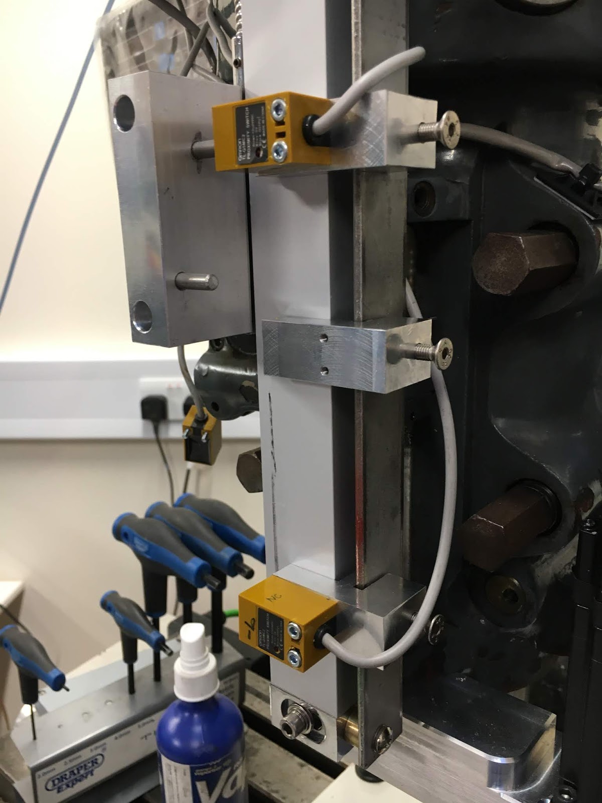
Here's the world's best photo of the underside of the table, showing the offending stops:


I am deducing that the top one (with dual ramps, closest to the slideways) is the home switch and the other one is the limit switch. Surely they are arse about face, as you'd want the home switch to be dual ramp on a good day. I may need to think about that more closely tomorrow. It's been a long day.....

Friday 15 May 2020

Bloody DMM Tech DYN2 servo drive losing its settings again....

What happened?
In the middle of buggering about with the encoder circuit, the Y axis stopped responding to the controller. The controller doesn't know any different, as it has no visibility of the actual position of the table. Oh, wait a minute.....

But sure enough, the step signals were getting to the control terminals of the servo drive (easy to check with a DMM), the ballscrew was being held on position, yet it wasn't moving in response to the step signals. WTF???

So clearly, as the servo was in control, there was no issue with the PSU or motor connections and the drive hadn't popped.

This has happened before on a couple of occasions. The last time was a few weeks ago on the X axis. When I connected up the diagnostics / programming cable on that occasion, I found that the PID settings etc had changed and the reason the thing wasn't responding to the step/dir inputs was because it had also magically changed the control mode to RS232 all by itself. I had left it on step/dir mode and it had been running for months like that, so it clearly has a mind of its own. I'm not sure I approve of that.

Let's have a look:
Got the progarmming / diagnostics cable connected up and the software running. Sure enough, the DMM software reported some funky new settings and RS232 mode. No wonder it wasn't responding to the step/dir signals. Here's a screenshot:


And here's the X axis in comparison - the way they should both be:


No, simply connecting up the diagnostics lead doesn't force it into RS232 mode. Let's just say this is fucking shit. How often is it going to randomly decide to change its settings without telling anyone?

I know these DYN drives are closer to hobby quality rather than industrial but FFS, get your act together, DMM !!

Encoder feedback for the Bridgeport / Newker 990MDCa?

What - closed loop control??
I can't decide for certain but it almost reads as if the Newker 990MDCa controller is capable of accepting external encoders for actual position feedback of the table and quill. The setup screen seems to contain parameters relating to this in the parameter range #200-220 within the "Other" page. They relate to allowable positional error (between set position and actual) and scale resolution (um per pulse) for the glass encoder scales.

I'm not 100% convinced that the system is offering a means of closing the loop. I can't help suspecting that in fact this is offering no more than a means of displaying actual position on the screen and generating an error if the difference exceeds those specified limits. The Chinglish manual really doesn't give much of a clue, although there is no mention of any PID controller which rather leaves me suspecting it's simply a "display and compare" function. There's only one way to find out for certain....

Check it out:
Some time ago, I created an interface board for the DMM Tech encoders. That was little more than a standard bidirectional line driver IC on a board in a box. But it allowed me to tidy up the installation of the DMM Tech servos, which would otherwise have required a crappy 9 way D connector hanging off the motor. Hardly industrial quality and no easy way to make it coolant / swarf proof.

Here was the wiring table I created at the time. It also includes the schematic I implemented and the pinout of the IC itself. Notwithstanding the inevitable cockup on the layout (yes, The Stupid Fat Bloke was entrusted with that task), it actually worked well. 


Conveniently, when I ordered the PCBs and kit of parts from JLCPCB and sister company LCSC, I got a set of 10 and built up half a dozen of them. Although I only printed up the required pair of housings, I don't need them to carry out this investigation right now.

This is it, marked up with suitable(?) names:


How to connect up?
Here's the pinout for the encoder feedback connections. 


You will note that this is a 26 way connector, not a 25 way connector. So in fact, it's a high density subminiature D connector. The likes of which I don't currently have. Bollocks. And the connector wasn't supplied with the controller, as it's not usually connected up. And no - a VGA cable is no use. For one thing they are male connectors at both ends and for another, they are 15 ways.


For the DRO scales:
The other end of the puzzle is working out how to connect the (single-ended) TTL signal from the DRO scale reader head to my line driver board. I will have 2 TTL signals - one for X and one for the complementary signal. These line drivers have 2 lines going each way, so one board should suffice for one axis.

Here's the post showing what is inside the DRO display unit. With luck, I should be able to work out the connections from here without having to dismantle it again.

Here's the inside view. The 3 axis connections are at the bottom of the main board. For each there are 5 wires. 


Inside the DRO display unit. Note that the ground / screen wire from the back of the connector is green, yet the connection to the protective earth is yellow. Go figure.


The pin allocation and wire colours are like this:


Strange "choice" of wire colour allocations!

Let's order some stuff:
Luckily, CPC stock these connectors at ~£0.87 each and can deliver next working day. Ebay also has some but the delivery would typically be around 5-10 working days. By then The Stupid Fat Bloke would have driven me round the bend with his impatience, so CPC it is, being cheaper (usually) than Farnell and RS.

But there's a min order value of £17.50 (before VAT) to avoid the £5 handling fee. And a £3 postage charge. So might as well get the value above £17.50 by adding some heatshrink tube, electrical contact spray, inrush current limiting NTCs etc.

Here's the 26 way high density Dsub connector from CPC Farnell. I seem to have some shells for that size connector, although I may never need them if this feedback isn't what I am hoping for.

I can take a cue from Centroid by using a similar spec for the inrush limiting NTC they use. CPC stock EPCOS (ex-Siemens) brand and my Bridgeport is a rather lower power machine than theirs, so I can afford to reduce the current rating somewhat. Here's the inrush limiter used on Centroid and the EPCOS equivalent from CPC Farnell. That should work.

That's me nicely upsold! Not much I can do until this stuff turns up, as there is no sensible way I can think to make connections to the CN13 connector on the back of the controller. Bollocks. 

Hold on...
That whining from The Stupid Fat Bloke just got to be a bit much to handle, so we had a go at connecting up the Z axis linear scale in then end. Couldn't get the thing to talk at all, so to get something happening, I connected up a Heidenhain rotary encoder (a spare from one of The Shiz's brushed DC servo motors). This has complementary outputs for A, B & Z (index). Worked straightaway and the "position" signal came up in one of the optional DRO screens. But no, it doesn't attempt any kind of feedback. Instead, it simply displays the error between the current position and the target position. You can set a max allowable error and from what I can tell, it will pause the move instructions until the servo has caught up, then open the tap again. 

Probably not a massive surprise but it constitutes the mild disappointment I was somehow anticipating. Buggerama and bastardisation. So at least I've answered that question, then. I may add a note to my version of the manual to sort of explain what I think we've got here.

Right, onwards and upwards onto something else.

Electrical noise filtering in the Bridgeport control system

Background:
About a fortnight ago I found that the X axis would occasionally start to creep as I watched. This would be a few 10s of microns every few seconds but that would add up over the course of several minutes to a noticeable fraction of a whole mm. So although it wasn't exactly a case of the axis running away on me, it would severely fuck up anything I tried to machine. It seemed to have a fairly random nature, which strongly suggested an electrical noise issue. I somehow doubt that the controller would be putting out random step signals.

I was able to rapidly narrow down one of the key elements of the issue. I removed the link between the cabinet ground and the logic ground. This significantly improved the situation but it didn't eliminate it. I then found that fitting a large toroidal core over the axis connector (where the step, direction etc signals come out of the controller) eliminated the remaining noise. 


Although this large toroid seems to have done the trick, it's not the best solution, so I got some Chinesium clamp-on ferrite filters of unknown parentage off ebay. These are often seen on computer cables, power supply leads etc and are simple enough to clamp over existing cables without needing to disturb solder joints etc.


Given that I clearly have some marginal noise issues, I'll go around the various signals cables and see if I can discern any improvement resulting from fitting these things, starting with swapping out said toroid for a Chinesium clamp-on jobby. 


In the end, I managed to fit all 10 of these things, along with a couple of almost identical ones from my box of cables - these ones from a couple of Ethernet cables of unknown heritage. They even fit over the lurid green drag cables. And they are pretty neat.

Step back a bit, Fatty:

Just like the servo drives on The Shiz, there is some level of noise on the X and Y axis drives on the Bridgeport. You can feel a low level grumbling on the ballscrews when the system is powered up. And given that this must surely imply some degree of movement of the motor, it can't be ideal. I'm guessing that the encoder feedback keeps the final position under control but it would be better if there was no noise to compensate for to begin with. This could be a common (normal?) problem with both (all?) installations.

Who knows, it may even be possible to improve on the installation on The Shiz itself. But let's see how we get on with the BP first, before we start getting too clever with ourselves....


Soooo - any better?

Certainly, it seems to sound a bit quieter. That migth be because I'm half expecting it to but certainly, when not at being asked to move, the motors are totally silent and there is only the vaguest hint of that electrical noise / quiet grumbling you almost always get on motor / drive systems. And if you try to move the servos around their set position, the zero error position where said noise happens seems to be very localised and the grumbling very gentle. Technical term there.

Anyway, let's repeat the Honda logo engraving job and see how we get on. Last time we were seeing stepped changes in the height of the engraved areas, to the point where the tool had lifted beyond the top of the material. The MCS machine origin had crept up, as could be seen in the return height of the quill.

So here's the acid test. For comparison, here's the previous example from 2 different angles:


The steps are quite evident.


...and here's the latest example. Looks pretty convincing to me. You can see the toolpath but there are none of the unintended steps in the height of the (machined) black surface.


This may not be quite up to professional levels of proof but I'm fairly confident that I've likely fixed the issue. The next proper job will involve machining some of your actual metal, so I will reserve 100% judgement until then. But for now, The Stupid Fat Bloke is pestering me to get on with something more exciting. For once, that seems reasonable to me.

Saturday 9 May 2020

Look for missing / lost steps on Bridgeport Z axis

Lost steps? WTF.
Yes, a week ago when I ran my first engraving since reassembling the Z axis on the Blidgeport, I found it was gradually shifting vertically as I ran the part. Didn't see this when cutting air, so I'm pretty certain it's due to noise from the VFD. Let's have a closer look, now I've got the Chinesium DRO working again.

Macro to cycle the Z axis:
I'm not about to manually run the quill up and down like some CNC wanker. Instead, a short g code file will do the trick:
N5   G54 
N10 G00
N15 Z0
N20 Z-100
N25 G04 P500
N30 GOTO N15

Or words to that effect. The G00 ensures a reasonably fast move, assuming that this would be a worst case feed situation. The G04 is the "pause" command. I need time to read the DRO and DTI when the quill is at full travel, being a human and all that. Then it loops back to the beginning endlessly until you hit reset.

Seems to work as intended:


With the VFD running but disabled, I'm not seeing any naughtiness. That is likely to happen when I start the spindle.

Oooooff!! Now the Chinesium DRO has started to talk bollocks. It's reporting 360mm drift. Sort of thinking that's not due to missing steps on the Z system. Sod it. Looks as if I'll be relying on the Mitutoyo (mechanical) DTI...

Turn it up!
Right, let's enable the VFD and get the electrical noise cranked up. I'm trying to recreate what I saw a week ago before I change anything, so I've not got any noise filtering slapped on yet.

Well, that's not doing much. So let's add 100mm G00 moves on X and Y, as well as 3000rpm on the spindle. Then cycle in a loop as before. I've moved the DTI to the head, as the table will be moving 100mm in each X and Y direction....


Hmmm. Not much going on here, even after almost an hour. Haha I suppose I could say I am almost going round and round in circles.

If this persists, I may be forced to re-run the original program. I'll have to decide if I should add noise filters first, as I have a life to live and plan to fit them anyway. That's not quite the ideal outcome, as it suggests I have a marginal condition here, rather like an intermittent fault. Not seeing the issue for now doesn't mean you've fixed it.

Revised Z axis limit and home switch assembly for the Bridgeport - make and install

Let's make up the limit / home switch assembly parts:
First, chop up some loominum. This is some 6061 I got in Canada. Using The Shiz in manual mode, using the MPG to move the tool and table. I'm not about to spend hours of my life doing this in Fusion. Let's try to be sensible here.

That Korloy face mill with APGT inserts does a fine job. If you look closely, There's an interesting(?) interference pattern caused by overlap of the leading and trailing edges of the tool. This is due to my manual operation of the MPG, resulting in variation in the tool speed across the workpiece. You wouldn't normally get this when using CNC mode / constant feed rates etc.


Being careful to ensure the surfaces are square and the 3 blocks end up the same size.


It's a "90 degree" cutter, so cuts nice shoulders too. I'm always shitting myself when holding multiple parts in the vise like this, as you can't be certain all three parts are actually being clamped equally. A loose part could send a part through the window, destroy the tool and fill my underwear with mud


4mm carbide end mill at 5000rpm to create the slots, stopping occasionally to prevent recutting / tool breakage. Mostly, the swarf was ejected in a stream, so didn't need to do much of that:


Then drill and counterbore the various holes for the fasteners and deburr with the Noga tool.


Once I'd found suitable fasteners, it all just bolted together. It happens sometimes.


The two studs are the targets for the proximity switches. These are the +L and -L limit switches. They are triggered by the "low" stud (nearest the scale).


A 10mm spacer lifts the Z0 (home) switch so it is triggered by the higher stud.


Looks OK. It's not exactly up to professional standards but I can't be bothered to spend more time on this than necessary. It should do the trick.


Reminder - if you don't fully tighten the ballscrew nut, it will fall off (along with the key) when you start to exercise it. Luckily I had milled some 12mm flats on the ballscrew and a couple of holes in the nut for this circlip tool. 


Setup - what is the end result?
Part of the plan was to maximise the range of movement by allowing a larger range of movement for the proximity switches without them hitting something. So the last part of the setup is to set the positions of hardware limit switches (+L and -L) at the physical extents of movement, then program suitable software limits, then set the home switch position.

Obviously you need to set the limit switches somewhere short of the point at which the mechanism hits some form of hard stop. And the home switch needs to be seen before the hardware switch is activated. All in all, the practicalities of switch operation etc mean that you end up with less software programmed travel than the extents of physical movement.

With the classical Bridgeport quill setup, you can just about manage 125mm (5") of movement in manual mode. So something like 115mm of software limited movement would be a great result. In the end, I managed 110mm, to avoid running into the hardware limit. The alternative would have been to slow down the home seek speed, to reduce the overshoot and thus gain a few mm of home position. 110mm will do for now and it's almost an inch more than the 90mm I had with the old system.

What's next? Good. Now that's in place I can move on:
  • Check the calibration of the controller - how does the controller DRO compare with the glass scale DRO, which I take as the word of god here?
  • Get an idea of the backlash. So far I'd estimate about 50-75um ie 1-2 thousandths of an inch in old money. That's probably as good as I should expect.
  • But above all, let's try to get to the bottom of the creep issue on the Z axis. After running the engraving program (Honda logo etc), I saw gained / lost steps. Now I have a means of catching it and investigating the cause and a suitable corrective action(s). Pretty sure the VFD noise was something to do with it....

Monday 4 May 2020

Z axis DRO scale mount - and revised home / limit switch concept

Background - DRO scale:
As noted, I delayed (re)fitting the Chinesium DRO scale from the Z axis, as it would have impeded access to the new ballscrew assembly. However, it's part of the final assembly and I'd like to be able to get a reasonably accurate measure of the absolute position. That will expose the accuracy / backlash as well as show up any missing steps or axis creep.

My original concept was implemented before I started the CNC conversion and picked up the quill position from the original feed trip mechanism. I then designed a steel ballnut yoke for the CNC conversion and was able to connect the DRO to that without difficulty.

The current arrangement for mounting the main body of the scale is simple and sound, so I plan to retain that. It picks up on a couple of flat, coplanar surfaces that are present on the std machine. From here it looks simple enough to make a bracket to connect the final ballnut yoke to the DRO scale slider.


Limit and home switches vs quill travel:
The other key element of this assembly is the arrangement for mounting the home and limit switches. I've made an effort to maximise the movement range of my revised Z axis assembly, as it's always an issue with turret / knee mills. I struggle with this on The Shiz as it is - and the BP has even less movement to begin with. The std BP manages 5" (aka 125mm) of movement and I'd like to preserve as much of that as possible, notwithstanding the unavoidable loss of movement due to the need for the limit and home switches to have a few mm of margin to work within.

The existing switch arrangement has resulted in lost movement - I can only get ~95mm, yet the mechanical parts are capable of closer to 120mm. That represents a loss of an inch or so - or 20% of the total. Not good. The reason for that is that there is no room for the switches to move before they clash with the head casting. They are maxed out here, with no possibility of further improvement.


So let's have another go, rather than bodge up the existing parts. And try not to get too carried away. I have a life to live and this doesn't need to be perfect.

New concept design:
I have the head assembly already set up in Fusion 360. So firstly, let's delete the old stuff and create a new bracket, keeping things nice and simple. This is little more than a strip of steel with a few holes in it:


The scale slider just needs a small spacer to connect up to the yoke:


I can mount a simple strip of 1" x 1/8" steel strip on the side of the DRO scale body using existing holes in the end caps:


Then design in place (within the Fusion 360 assembly) a slider component that will fit over the rail and lock in place with a set screw. Something like this:


The middle one will be the home switch. As it needs its own target, I need to mount it at a different height to prevent it triggering from the limit switch target. The (black) spacer should do the trick, while leaving the sliders otherwise identical.


This will be the final assembly. The switches can fit anywhere between the ends of the rail.


Fair enough. Enough talk - let's make the fucker.
The bracket is simple enough to knock up with the bandsaw, belt sander and hand drill:


With the various spacers flashed up, it all seems to fit together nicely. It even clears the 4 large bolts, although they have no obvious purpose on a CNC machine.


Doesn't look too silly:


It's not going to be quite as compact as the previous version but there again, the previous version didn't allow enough movement, so what do you expect?

Next - make up the sliders and the target piece for the proximity switches.

Final assembly and test of the spindle nose adaptor - RESULT!!

After the recent distraction caused by the 3D scanner, resurrecting the 3D printer and buggering about with the throttle bodies for my Honda...