Sunday 27 May 2018

ATC for The Shiz!

Last weekend I acquired an ancient automatic toolchanger (ATC) from "Steamwise" Mike who lives not far from me. He has a similar Shizuoka (he has the more commonplace AN-S, unlike my oddball AN-SB) which is 90% the same construction as mine. It was also a Matchmaker CNC machine with the Micon controller like mine. IRRC, he runs UCCNC software, which was developed by the same Czech company that developed the servo drives I used in my retrofit. Seems very happy with it.

The front of the ATC unit has a sticker that boasts US patent # 3872743A from Feb 1973, held by Fadal. It's expired now but still available for download and of course it explains the operating principles. Some patents are very general and don't go into specifics of actual examples but others may resemble descriptions of actual products. This one seems to resemble the device sitting in my garage, so could be pretty helpful.


It seems that the ATC was helpful in the early development of the Fadal company - the ATC design (and presumably patent) was sold to Dana Summit for a decent sum ($75k), which enabled them to further develop their core CNC technology. This became known as the Bandit Quickdraw. Fwooaaar.


Interestingly, the history says "The problem we had with the toolchanger is that we over marketed and then couldn't meet the demand," says Dave. "Because of that, the guy in England that we were marketing too, Matchmaker, copied our toolchanger. They apologized for doing it, but did it because we couldn't deliver to them." Doesn't say where this one was made - but judging by the imperial fittings and US compts, it seems to be an import, so probably a "genuine" example.

I haven't been able to find a pukka manual for this particular ATC. It seems to be a very early version, probably dating from before the sale to Dana, judging by the front panel (marked "Fadal"). There is a manual for a Dana Summit version but when you look at the electrical schematics, it becomes obvious that the later versions were more productionised, with stuff like PCB connectors for the interconnects (mine has wires soldered directly into the PCBs) and triacs instead of relays.


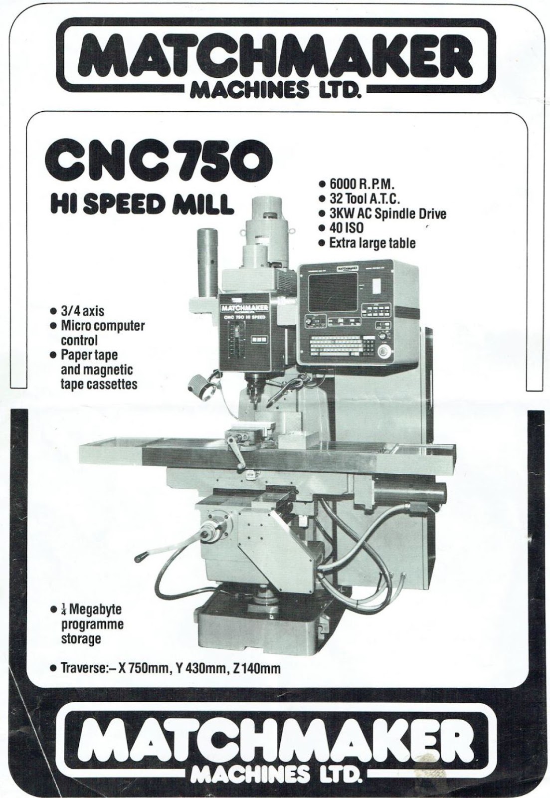
My machine came with the optional power drawbar and chip tray (and engraving software) but not the optional ATC. The brochure only shows the basic setup but mentions a "32 tool ATC":


Here's my machine in its current form, showing the side of the ram where an ATC would fit:


This is the ATC on Mike's machine (with the cover removed), before a couple of monkeys were set loose on it:


Now to remove it from the car....

Saturday 19 May 2018

Y axis moves!! Tuning the DMM servos - overview

As I've got the Y axis bolted together and the belt is fitted and tensioned, I thought it would be rude not to flash up the controller and give it a spin.

The program I have loaded in the memory makes a variety of X, Y and Z moves but it's clear that the default PID settings for my Dyn2 drives are somewhat "suboptimal". It seems to have a bad case of the DTs or possibly Parkinson's.


Link to the servo drives here. And the software download page.

The DMM servo tuning software is designed to help with the process but it requires some calculations to determine the ideal settings. For now, I just fiddled about and ended up with a better ie more stable result.


I'll come back to this when I've done the sums and have something to go on. The CNCdrives tuning software that supports the brushed servos on The Shiz has some nice features that display the demand and actual motor movement, so you can observe how the overshoot and steady state error are affected by the settings. I suppose the DMM boys are taking the more theoretically correct approach by calculating the moment of inertia etc and calculating the appropriate gains.


This is how they describe the process:


Back in Jan 2016, I started a spreadsheet to do these calcs. I'll need to review them and finalise the values. Looks as if I got a little way along the road with it, although it is rather devoid of the calculations and actual values. Details, I know!


I can use their example values in my spreadsheet to check my sums make sense.


Update:

In fact, it seems the software has been updated since I made my copy on the network. The latest version looks a lot less flakey, judging by the manual.

Here's the autotune page. I ran it OK but I have to say the resulting settings (gains of 8, 7 and 1) seem some way off the mark.


I over rode the settings manually using the slightly snazzier screen:

Clearly some work to be done on my part....

Rewiring the Y axis motor - grinding back the Y axis ballnut - reassembling the DRO - M12 nut

Grinding the Y axis ballnut flange:

When I fitted the Y axis ballscrew, I failed to check the movement range. If I had, I would have noticed that the saddle wasn't able to move right to the back of the knee. Clearly something is binding and given that the ballnut is the only changed component, I suspect it's fair to assume that the ballnut flange is hitting something.

In fact, you can see into the inside of the knee assembly by sliding back the cover. The problem is pretty clear - as expected, the flange of the new ballnut is clashing with the Z axis crank shaft, where the bevel gear bearing is housed:


Whipping the bearing housing off the front of the knee reveals the ballnut mounting screws. The (larger) flange is visible.


It's quick and easy to withdraw once the 2 screws have been removed. It was nicely oiled, so the lube pump seems to be doing its job.


The yoke (ballnut housing) has a relieved surface at about 8 o'clock. It's obviously there to provide clearance to the bevel gear bearing housing.


I'm going to be removing the corner of the ballnut using an angle grinder. The last thing I want is grit getting into the ballnut, so I wrapped the ballscrew / ballnut assembly in clingfilm.


A piece of steel tube to protect the exposed ballscrew, in case I have a wobble or a slip.


And a little booth to contain the grit and sparks, to prevent them from getting everywhere.


Like a lot of my work, it's not pretty but will do the job:


Reterminating the motor phase connections:


It took a few sessions with the angle grinder to get the flange ground back. There's a lot of heat generated, so in between being nasty to it, I let the ballnut cool down and turned to the motor. As mentioned before, I wanted to get rid of the Mate And Lock style connector in the motor wiring by soldering the cable directly to the stator. Like this. The yellow wire is the ground connection to the motor housing.


Job done. Haven't tested it yet but 95% confident it should still work.


Reassemble DRO scale in new position:

Drilled and tapped the new M6 holes, shortened the cover and refitted the scale. Looks good to me. Apart from the "machining" of course.


M12 nut for handwheel:

Still haven't got round to making a nut for the Y axis handwheel. The ballscrew was machined to my drawing, including an M12 (fine) thread for the locknut. That's a non-std pitch (1.5mm), so I need to make up a nut for it. I have the required tap and some handy hex bar.

Drill and chamfer front, then partially part off:


Thread and back chamfer before parting off finally:


There:

Friday 18 May 2018

Trial fitting X and Y axis brackets

Made a couple of spacers to set the position of the Y axis pulley and handwheel. The motor fits nicely..


The X axis housing bracket thing seems to be about right. I'll need to make up a couple of spacers for this too. The bore is 16mm clear (to fit over the end of the ballscrew) and the outer diameter around 25-38 mm.


Can't fit the belt in either housing yet, as I don't have the bearings that form the tensioner. Rather than moving the motor in slotted holes, a jockey pulley (2 bearings) is mounted in the slotted hole. 

The bearings are 608-2RS ie "608" bearing with double seals. Ordered them today (Friday). That's 8mm ID, 22mm OD and 7mm thickness (length). 2 of those buggers will give me a 14mm wide jockey pulley. The 8mm hole will house an M8 bolt that will ride in the slot.


Here's where we are right now. Seem to have a couple of axes almost ready to go. I want to get them moving before I get busy with the Z axis.


Saturday - the bearings arrived. Not bad. The standard carriage was described as 2-3 days, so next day receipt was an unexpected bonus. 


X axis bearings in place. Seems the bearing manufacturer has rights to the use of the "Dunlop" tradename.


X axis fully assembled. Looks good.


With the handle fitted but no cover plate for now.


Looks good.


Thursday 17 May 2018

Bollocks - Y bracket cockup - machine heal thyself!

The Y axis bracket looks as if it should fit on / together OK. Here's what it looks like at first glance. Doesn't look too bad....


...until you try to bolt it to the knee. At which point it becomes clear that the motor is about 3mm too close to the knee casting. Clashes with the knee casting:


Holding the motor body perpendicular to the bracketshows how much it needs to move:


I can just about get a 3mm drill into that gap


Not much danger of modifying the bracket or the motor to overcome the problem. No. Instead, the pragmatic solution seems to be hacking away at the casting to make room. Or technically "machining" a shallow indentation using a router. 


I planned on moving the Y axis DRO scale back a bit anyway - I need about 15mm:


There is the required space at the other end. I'll need to drill and tap a couple of new M6 holes.


Before whipping this lot off to machine the knee, for the record, here's the position of the fixing screws relative to the adjustment slots:


So, back to the machining. I have 4 angle brackets, so I've managed to cobble together a contraption that will hold my small Bosch router at the correct orientation and be able to move it in and out in the X and Y directions using the table controls. And the Z axis by loosening a couple of bolts and shifting the tool periodically. The router is bolted to the loominum angle plate using the original M4 holes in its base. I've checked that the table can provide the required range of movement without fouling anything. It's not going to be pretty (or quiet) but there we are.


After a bit of last minute adjustment to give the required range of movement, we are ready to go:


It makes a lot of sparks.


Part way through. I won't get any marks for style. The vertical adjustment is by loosening the bolts and raising or dropping the whole chebanc manually, so pretty hit and miss. The right / left adjustment is by eye, so also pretty scrappy.


It packed in part way through. Turns out one of the brush retainers had unscewed. Luckily it had landed in the chip tray and I was able to find it easily.


I made a couple of passes with 2mm axial DOC and full width , which was possibly a bit aggressive. The cutter didn't last very well but I had a spare and at £6 a pop it hardly broke the bank. You can see it got pretty hot but there again it was probably rubbing rather than cutting by this stage.


Here's the final result. Not pretty, as expected. But the motor fits nicely and nobody died. 


Now I need to remove the scaffolding, clean up and reassemble the DRO scale, motor bracket etc etc and resume the assembly / fitting process....

Final assembly and test of the spindle nose adaptor - RESULT!!

After the recent distraction caused by the 3D scanner, resurrecting the 3D printer and buggering about with the throttle bodies for my Honda...