Sunday 12 June 2022

Swap the turret hoses, clean the coolant tank and replace the pump

Let's get these hoses and couplings changed. First, I need to remove the BSPT-BSPP couplings.


Then fit the replacements and the new hoses.


That went well but I mustn't forget the 3 short hoses that run from this manifold block to the turret. I didn't buy those first time round, as I wasn't 100% sure that (if) the first lot would fit. Fortunately they do. They run from the rear of the turret....


...to the manifold black:


There. Ready for the new hoses. The 3rd (middle) hose is for the coolant feed.


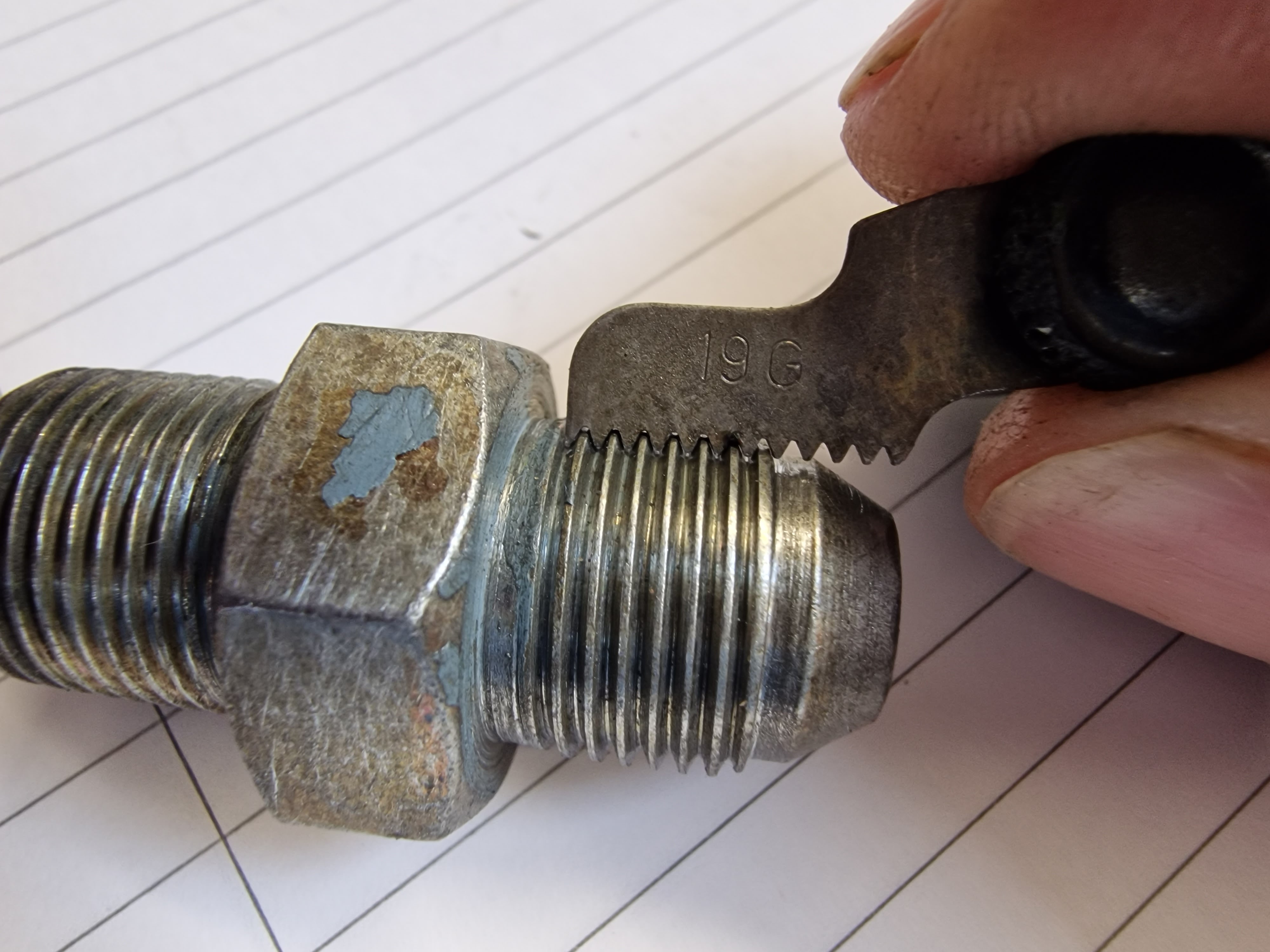
When I'm ordering up new hoses and couplings, I should replace the small power drawbar hoses. I know what will happen if I don't.


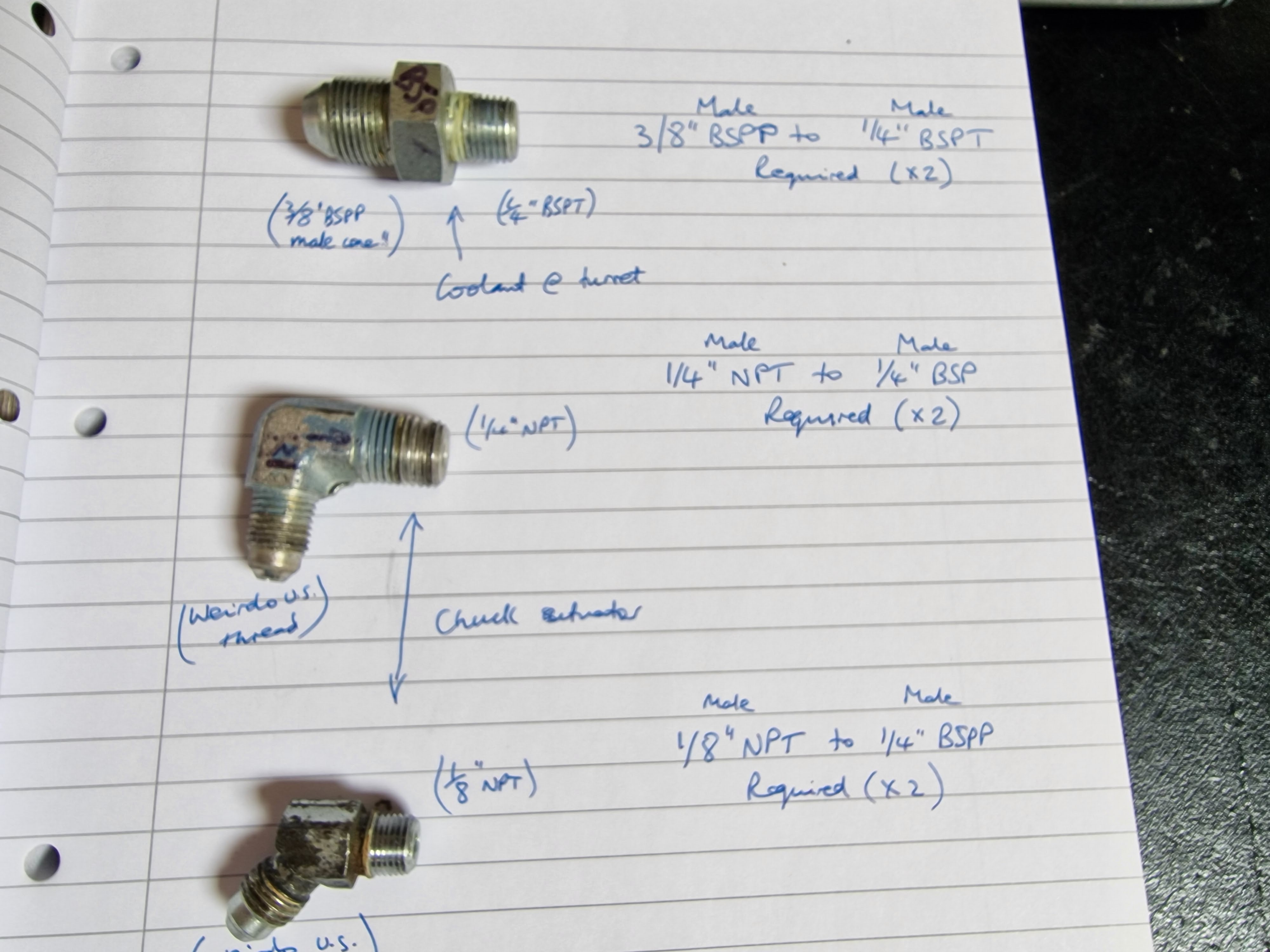
Like their bigger brothers, they have weirdo couplings. What are they?


As ever, there's a veritable cocktail of fittings here.


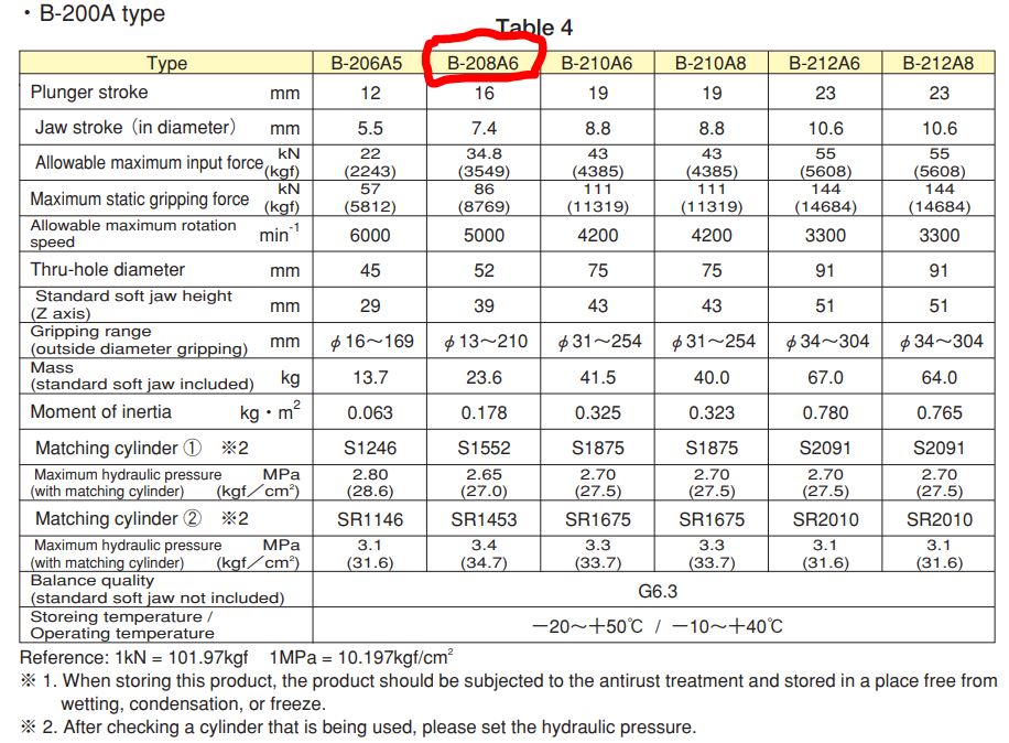
Pneumatics Direct have what I need at pretty decent prices:


Here's the link to one of the pages eg for the BSPP Male x NPT Male adaptors.

Not forgetting the actual hoses themselves. I could probably use 1/8" BSPP hoses but the adaptors seem to be much less available. So instead I'll use 1/4" BSP fittings and hoses.

This guy is just up the road but his prices are very good and the service was blisteringly fast. I ordered the 3/8" hoses on Sunday last week and they arrived Tuesday morning. Hope the next set are as rapid.

Coolant tank and pump:
While this lot is happening, let's take a look at the coolant tank and pump. It looks as if The Creature From The Black Lagoon may be in there.  


Here's the pump. Some Mercan motor from Chicago. 1/4HP, 2 pole / 3000rpm machine. 


Claims to be configurable in star or delta, according to the diagram under the terminal cover. 


However, there are only 3 wires and a rather un-Mercan-looking terminal block. Looks to me as if this has been rewound. Would they have done that? But if the entire motor had actually been swapped, it seems unlikely the replacement would have been made in Chicago. Closer investigation required....


The shaft was a little tricky to remove but I got there. There's a stainless shaft extension and an aluminium rotor. 


But wait, it shouldn't be pissing shitty brown water out of the electrical enclosure. WTF is going on? Off with the long screws that hold the casing together.


Hmm, yes, the thing is swimming in water. I guess I could dry the stator out simply enough but let's take a closer look before doing anything major. The sealed bearings look OK....


Let's check out the (now clean-ish) coolant tank and swarf separator.


Here's where the pump sits. 120mm aperture...


...~140mm (5.5") PCD for the fixings...


...and a depth of around 240mm from the flange mounting face. 


Hmm. That old pump has a shaft length of only 150mm. So the pump can only access coolant above a depth of 110mm. The bottom 4" or more can't be used before the pump runs dry. Can't imagine they actually designed it that way. There's a shallow dam on the floor of the tank to avoid swarf getting to the pump, which would be rather redundant if they never expected the pump to be closer than 4" from the bottom.

The rotor and shaft extend directly from the motor shaft without any outboard bearings, so attempting to extend the pump by 4" would be a dumb exercise. Chances of managing to get it running true are sub zero. And hacking the cast iron housing to extend it by that 4" would be equally dumb.

Right, I consider a rat well and truly smelt here. This is surely a replacement pump - that has also been rewound, FWIW. It may fit the aperture and the fixings but I can't imagine the original didn't reach anywhere near the bottom of the tank. And given that the motor looks pretty sad, I think I'll just get a replacement with a full length (240mm) shaft and be done with it. That alone will almost double the useful capacity of the tank from where it is.

How about this Vertex 1/4HP 240V single phase from Rotagrip - decent quality, single phase 240V, 240mm and 1/4HP. I will need to tap some more fixing holes (they are on a larger PCD) but I have the technology to do that.

Sunday 5 June 2022

Let's get some replacement turret hoses!

I need to replace the porous hoses that run from the hydraulic pump to the turret. Doubtless they are some weird US thread dating from the 80s. I'll need to remove them to replace them obviously but I also need to determine what couplings they have used.

Firstly, let's uncouple the hoses at the turret end. Access is tricky!


And also at the manifold block end.


What is the coupling? Well it's clearly 19 TPI. That's a pitch of about 1.34mm ie not 1.25mm or 1.5mm, so unlikely to be any form of metric thread. That isn't surprising given that this machine hails from the USA in the early 80s. The only thread I can find that uses 19TPI is the British Standard Pipe thread, which comes in parallel (BSPP) or tapered (BSPT) forms, depending if it's to be jammed into a hole or used with a hose coupling.

For reference, the taper plugs I bought to block the holes in the manifold recently were 1/4" NPT. However, the nearest NPT thread is either 18 or 20 TPI, so it's not one of those. 

Naturally, the hoses on the Tree also have a male (convex) cone on the male couplings and a female (concave) cone on the female couplings. Whereas the std BSPP males have a female (convex) cone and the BSPP females have a male (convex) cone. 

My solution is to get these adaptors (BSPP to BSPP adaptor and BSPP to BSPT adaptor) to replace the existing adaptors so standard hoses will fit. And these boys are offering a fixed price hose in various lengths https://www.ebay.co.uk/itm/124828855866?var=425886910766

The turret hoses are each 3m, whereas the long coolant hose is 6m long. To keep things simple, I've ordered 4 of the 3m long hoses and will join 2 lengths together for the coolant with BSPP / BSPP straight adaptors.

Thursday 2 June 2022

Kitagawa chuck!! So near and yet so far?

What's this about, Fatty?

Serious trouble on the UK Machine Tools Facebook user group again, involving a mouse, as ever. This time I've ended up with an 8" Kitagawa hydraulic chuck. These are the dog's bollocks as chucks go and although this is a rather old model, it seems to be in decent condition. Not bad for £200 plus £18 carriage.

Here's the chuck itself:


And yes, it even has an A2-5 adaptor plate (complete with fixing bolts), so it will bolt directly to the nose of my machine. What were the chances of that?


Might be fucked up inside but I can't see any signs of that. It appears to have been reasonably well looked after, apart from a few minor dings on the body.


And even better, it comes with a shed load of soft jaws (some new, mostly with a fair bit of life left in them) and a set of hard jaws in decent nick. 


And even better still, it comes with 2 sets of tee nuts. A complete starter kit!


So why the long face, Fatty?

Well, is a "collet closer", as provided on the Tree the same as the "hydraulic drawbar" expected by a Kitagawa chuck? Well, for one thing, it only needs to pull on the (3J or 5C) collet, whereas these chucks require positive push / pull actuation to open and close the jaws. This isn't just required to tighten or loosen then jaws but allows for both external and internal gripping.

The Tree collet closer isn't well documented but it has 3 fingers (levers) that compress a set of Belville (disk) springs to release tension on the collet closer drawbar. Releasing them causes the springs to tension the drawbar and pull on the collet. Is that it? If so, then I've wasted my time, money and excitement here. I could be looking at a chuck that fits my machine but won't actually function....

NO - LIGHTEN UP!! These springs are only provided to define (limit) the tension on the collet drawbar when the collets are tightened. It does this by compressing the springs by a controllable and consistent travel at the end of the (tightening) drawbar movement. 

We can estimate the movement that the Tree collet closer generates on the springs at the end of travel. The fingers provide a reduction ratio and the initiating movement is caused by sliding a conical body up inside the fingers.


Here's the drawbar with the conical feature and one of the actuating fingers. You can see the range of movement from the witness marks. The entire drawbar is moved axially by the actuator, by something approaching 30mm or so:


Here are my fag packet calculations, which estimate around 2.3mm of axial compression (compression), assuming zero clearance at the start of movement. 


The collet tension is intended to be this movement times the spring coefficient of the combined stack of Bellville springs, whatever that is. The Tree manual simply tells you to adjust the engagement of the drawbar with the collet by screwing it in or out "until the desired gripping force is obtained". Very helpful. However, in my case, the Bellville springs play no part in the operation of the Kitagawa chuck and I don't plan to play with collets at this stage - perhaps later, once I can find a (replacement) adaptor to run 5C collets in the 3J spindle nose - you may recall that The Stupid Fat Bloke machined the original one out, as he was unable to remove it without risking damage to the spindle and/or bearings.

So, will it work on the Tree?

Pretty convinced it will. With the later(?) version of the collet puller / drawbar actuator used on my machine (as opposed to the one shown in the manual), I seem to have a pretty decent range of movement, with the ability to apply both tension and compression force to the drawbar, said forces being controlled by the hydraulic pressure from the pump.

There's a big fuck off bearing here that handles the thrust load. I removed it from the drawbar earlier (during the initial dismantling) but the circlip on the drawbar shows where it sits. That bearing (shown here) is moved in and out axially by a hydraulic piston and yoke:


The bearing doesn't sound completely happy, so I will need to obtain a new one. However, the piston travel seems to be ~20mm (I saw 30mm above, mind), judging by the witness marks on the push rod. The mechanical advantage (lever ratio) is 1:1, so that will result in around 20mm of movement of the drawbar. Is that what the chuck needs?

I assume this chuck is very similar to the current B-08 model, for which there is support documentation available. In particular, the "Instruction Manual" gives us all we need to know. The stoke for the B-208A6 looks to be closest to mine. The A6 refers to an A2-6 spindle nose, rather than the A2-5 I have, otherwise it's surely the right model to refer to.

And indeed, the required stroke is ~16mm at the drawbar, resulting in ~3.7mm radial movement of each jaw. Sounds as if the chuck gods have smiled on us here.


Not sure why but Table 5 suggests ~2mm stroke. Whatever. As long as we give it the required drawbar movement and force, we will get the intended operation.


What about the drawbar - does it fit?

Does it shite. Of course not, as it's intended for a 3J collet or a 5C with the supplied adaptor. Both the drawbar and the chuck have female threads of course. So I will need to make up a short male-male adaptor that mates with the drawbar and the chuck.

Seems the current B08 chuck has an M60 x 2.0 female thread, although mine measures at M50 x 1.5. No problem, as I will make it up on the Bantam which doesn't care. If anything, an M60 thread might have been a bit of an issue with my A2-5 spindle nose. The current range uses an M55 x 2.0 for the A2-5 (6") version. 


Seems that a 3J collet has a 1.988"-20 thread. So that defines the threads. It's helpful to see that the 2" thread is pretty close to the 50mm one. All I need to complete the dimensioning of the adaptor is the length and diameter(s)....

Final assembly and test of the spindle nose adaptor - RESULT!!

After the recent distraction caused by the 3D scanner, resurrecting the 3D printer and buggering about with the throttle bodies for my Honda...