Retrofitting 1983 Shizuoka AN-SB CNC milling machine, Bridgeport mill, Colchester Bantam lathe and 1982 Tree UP-1000 CNC lathe with modern controls - and other workshop stuff
So, I chopped off another length of the 3/8" flat stock and prepared to have another go at the cover, with a view to getting the alignment better and avoiding any massive crashes this time. The main cause of the misalignment at the first attempt was the result of flipping the stock over half way through because of said crash. That and the fact that the stock width that was defined in the CAD / CAM wasn't quite right. This time round, I was careful to double check that the tool lengths etc were spot on - by jogging to Z10 in G54 with each tool loaded (G43 T13 H13 etc) and checking that a 10mm ground drill shank would just about fit between the tool and the work surface. I made certain the Martest (Haimer clone) was set up and used it to touch off on the back edge and top surface of the stock. All looked good. Finally, I managed to connect up a cheap (£20) and nasty retracting air hose I got from Lidl this week using a 3-way airhose adaptor, also from Lidl for £5. I have some air tools from the Wavedriver days, including a couple of nozzles. So now I can blow swarf clear if it starts to build up in a way that looks hazardous to the tool. With all the tools set up and the (slightly rejigged) programs on the USB stick, progress was quick. The total machining time is only 12 minutes (plus tool changes etc), so the whole job took me around 20 mins or so. M4 holes:
M3 holes:
Counterboring:
Milling out the middle fixing pockets:
Rough profiling:
Finish profiling:
Came out nicely, leaving just the matter of snapping off the tabs, sanding them flush and doing some minor deburring. Then manually tap out the M3 and M4 fixings. Job done! Not 100% perfect, but then I don't imagine anything ever will be. But certainly good enough for the likes of me.
So, everything set to go. WCS origin set at top left rear corner (more about that later....). What could possibly go wrong etc etc. First, rough out and finish the large hole in the middle:
This morning (Sunday) I loaded the code into the controller, did some last minute checks and hit the green button. The big hole appeared as planned. Next - the first drilling operation (M3 clearance drill). Copied this across to the controller, carefully forgot to actually load it into the program space and hit the green button. This reruns the program that was last used..... I was all fingers and thumbs this morning so I forgot to start the video. Pity, as it would have shown beyond any doubt that the jaws / teeth of a keyless chuck are well capable of machining loominum, with or (very rapidly) without a 3.5mm drill in place. It was a hell of a crash but nothing got irreparably damaged and no mud was made. It had been trying to machine the large hole (again), this time with a 16mm keyless chuck and 3.5mm drill instead of a stubby end mill holder with a 10mm end mill. Obviously the total stickout of the chuck and drill are somewhat greater than for the end mill. Bit of a scuff on the edge of the large hole where the body of the chuck tried and failed to burnish a large chamfer, so the best recovery plan seemed to be to turn the work upside down on the fixture and have another go. After all, the fixings are symmetrical. Start again....
After that recovery, everything seemed to go well enough. Luckily I checked the tool offsets before proceeding again, as I found that the drill lengths were all to cock.
2D Profiling the middle M3 fixings:
Roughing out the external profile:
Counterbore the four M4 fixings:
Chamfer / edge break:
Finished:
So finally, I have the cover plate machined. Still held to the remaining stock with the tabs I added in Fusion CAM. But the fit isn't quite as perfect as I'd have hoped for given that all the CAD and CAM work was done in Fusion - no manual operations or guesswork involved. WTF?? Looking more closely, there's the best part of 1mm of misalignment between the mating edges where the cover and bracket come together. If I assembled them with their fixing screws (I haven't tapped the M3 and M4 fixing holes yet), that offset would be plain to see. And the chamfer on the big hole is variable around the circumference and the chamfer down the "bottom" edge is almost non-existent. I've tried to line up the fillets and taper profiles here. The misalignment is "readily evident". Bloody annoying, not least as it's almost certainly my own stupid fault.
There's a misalignment of the best part of a mm at the bottom:
And a similar gap at the top:
So what happened? It's not rocket science although it caught me out:
I'd dimensioned the stock body as exactly 4" (101.6mm), whereas it's actually 101.36mm, ie 0.24mm undersize. The main bracket body is 101.82mm, ie 0.22mm oversize. These are both pretty good tolerances for extrusions but that's 0.46mm difference straight away.
Stupidly, I'd chopped and changed on the WCS origin front:
For the main body, I started out with the origin at the top back left on the basis that the stock was pretty close to nominal (actually 0.2mm oversize).
When I turned the body over to machine the top side, I transferred the datum to that side by using the central large bore, given that it's probably the main feature.
Then, when it came to the cover plate, I randomly chose to use the top back left for its WCS origin, figuring that it didn't matter as long as I aligned the rear face of the stock with it correctly.
Swapping over the datum origin when I flipped the main body probably wasn't an issue - in fact it was probably the recommended method. But touching off on the rear left (top) corner was dumb.
And much of the problem arose because I flipped the cover stock over after my crash. As I set my datum on the rear edge, any difference between the modelled stock and the actual stock would now appear as a misalignment.
I should probably have:
Ensured that the main body stock was truly centred eg defined the origin on the stock centre line, not the top corner.
Defined the WCS origin as the mid point of the large hole and positioned the centre line of the actual stock on that point. That way, the cover will be mid positioned.
A couple of other things:
The side pockets for the central M3 fixings have a little nib in the middle. The 3mm end mill did a nice job creating the pocket but didn't clear out the floor across the whole area. That's presumably the result of using a profile toolpath, rather than a clearing operation.
The M3 and M4 clearance holes did not even break through. Clearly some problem with the drill lengths.
What to do? This is the plan:
Make another cover blank with fixing holes to suit the existing fixture.
Define my WCS origin (particularly the Y offset) to
Hacked off the required lengths of 3/8" and 1-1/2" stock, deburred and clamped it up in the vise. set my zero to the top back left, as per the CAM.
Then drilled it out 7mm through to 15mm below the surface of the bottom "fixture" part, with a simple CAM deep drilling (pecking with full retract) operation. Then into the Blidgeport to drill out the plate to 8.0mm (to clear an M8 bolt) and tap the fixture M8 with a spiral flute machine tap. Job done, work mounted and ready for some machining:
But first, let's actually finalise the diameter of the large hole in the cover. This is to allow the ballscrew and handle to pass through the cover plate. Currently it's 36mm dia, which is a placeholder number I just pulled out of my ass so I could model the assembly up in Fusion. I suppose I could accidentally machine it with a 36mm hole but the chances of it being right seem slim. The required diameter for the large hole is about 48mm or so. It has to clear the boss of the hand wheel. It's a cast iron wheel and the boss isn't fully machined, so the dimensions are a bit ill defined. I will turn it down to a consistent diameter when the time comes to fitting the stuff to the machine. And the cover plate is 3/8" thick (almost 10mm), so I'll probably also need a modest spacer between the wheel and the pulley. So I modified the CAD to incorporate this final dimension, reposted the g code and got out there to do the business.....
The cover plate is made from a piece of 3/8" flat stock, 4" wide and as long as the bracket itself, with the same profile. So not much sense in trying to clamp it at one end. Instead I'll have to clamp it down to something solid, or even better, bolt it down and machine it using sacrificial tabs that can be sawn and filed away afterwards. Simplest solution is to bolt it to a piece of the same 4" x 1-1/2" stock used for the bracket itself. I reckon that can be held in the vise and the cover plate bolted onto it with 4 x M8 bolts. First, model up the cover plate with some extra length for bolting down.
Then use this to create a "fixture" ie a length of the thicker stuff the same width and length. Drill through both with 7.0mm drill (good for M8 tapping). Then manually drill out the holes in the cover plate to 8.0mm for the bolts. Once the holes are tapped M8, I can bolt them together, set up on the machine and get machining.
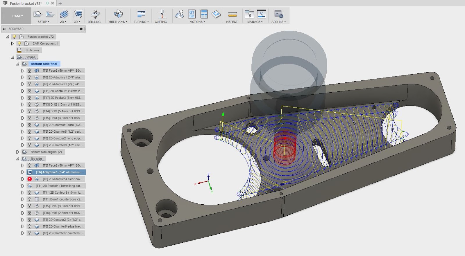
Do the heavy operations first ie boring the large central hole, then the drilling, pocketing and counterboring operations. Finally, cut the outer profile (leaving tabs) and finish off with chamfering. The CAM looks relatively simple. Although there are 11 operations, there are althoughonly 7 tools. NB: I notice that my tool numbering is a bit suspect. In creating some new tools, I've ended up duplicating some tool numbers. Must fix that or I will risk crashing some tools!!
It's good to have the stock modelled in simulation, with the CAD model also visible. Then you can turn the post-machined stock on and off with the check box and check to see if the final work piece has all the desired (CAD model) features. That's particularly important for the chamfers etc which can be a bit tricky to set up with the correct offsets etc. This what the CAM simulation believes will result:
I'll use the band saw to remove the sacrificial stock and then use a 2D Contour to clean up and leave a fillet on the end corners. Modelled a simple piece of stock to represent the end of the work: Then used the 2D Adaptive to machine back to the required profile. I assumed a 3mm stock stickout, so as long as its less than this, it will do the trick.
It's a deceptive view but the origin triad is actually at the bottom plane in the centre of the large bore. That should align it with the existing features on the other side. Mark out and chop off the sacrificial lump:
So, having faced off the top surface and prepared / scoffed / cleaned up after the evening meal, back out there to finish the job off. Seemed to be going pretty well, although the first 2D Adaptive roughing pass to clear out the cavity did a couple of naughty moves. This is clearly due to the presence of the 2 countersunk holes in the model. It didn't seem to matter what I did in terms of selecting contours etc - it would still insist on trying to take a large chunk of material at that location. I'd noticed the toolpath looking a bit odd there when I ran the simulation and sure enough, it wasn't very comfortable to watch. Luckily I managed to fumble the iPhone and although I pointed it at the work throughout, it turned out I hadn't started recording. Not for the first or last time.... Luckily the tool survived the condition but I stopped the machine and redefined the roughing as a 3D Adaptive.
This did the trick, although it now spirals into the centre of the work rather than move in from the large cavity. No problem.
This left a fairly reasonable finish, given that it's a corncob-type roughing tool:
Then finish the cavity with a 2D Pocket to clean up the bottom surface. The tool defaulted to its 5000rpm setting (set in the tool table by me). I've been dialling it down on most operations but it was fine here and left a good finish. Luckily I managed to forget to start recording again but you can see the surface finish is pretty good.
Similarly, I used the same tool to clean up the walls using 2D Contour. It zips along when running at 5000rpm and the swarf piles up behind the tool.
That's the cavity done and it looks pretty decent:
Counterbore the holes:
Drill M4 tapping holes:
Drill M3 tapping holes:
Chamfer / edge break:
Pleased to see that this chamfer worked out ok, given that it is right up against the wall (touching in the CAD model):
Good stuff. Next:
Chop off the extra stock and machine the end / fillet the corners.
Tackle the cover plate. This will require some form of fixture to hold it given that it's long and thin.
As I seem to have completed the bottom side operations without perpetrating any further outrages, it's time to set up the work for machining the top side. This entails roughing out and finishing the cavity between the cylindrical bores to form the space for the drive belt and tensioner pulley. There will also be some tapped holes for fixing the cover in place and some edge breaking / chamfering to finish it off.
As before, I will use the 3/4" hogger to rough out the bulk of the material, followed by a finish operation with the 10mm long series carbide end mill. With the cylindrical bores already machined, it shouldn't be such an issue clearing the chips out of the way. I now have my Jeton coolant hose system, so if I can arsed to get around to fitting it, I'm hoping it will be easier to place the coolant streams where they are useful and end up with less of it on my clothes. The WCS zero for the top side is in the centre of the large bore, coincident with the (now finished) bottom surface of the part. I know the vise is still set up at the same height as the bottom operations, so I can just go 37mm below the previous G54 Z0 plane and set my new G54 Z0 there. And I could even check that I've got down to flush with the bottom face. Previously the stock height was bang on 38mm and the bottom ops took that down to 37mm. The final height will be 36mm, taken off in 2 facing passes again. And like last time, I've entered the heights data for all operations into my spreadsheet to determine the best table (knee) height, along with the quill extension for the G54 Z0. Without that, it's unlikely I will magically find a G54 that will accommodate all the moves and tools within my limited quill travel range.
I suspect my T01 reference tool is too short. It has the shortest stickout in the tool table and with the operations I've specified (including T01 for setup), I'd need over 150mm of quill travel. I think the limit is around 155 but the soft limits are currently 150mm. The solution is actually to touch off on the top surface of the part (which is Z37), entering the approved coordinate there ie 37.000mm. In the spreadsheet, I simply entered Zmin and Zmax as 37. The ideal G54 Z0 height is then around G53 117mm ie with the quill moved down 117mm from top position.
The G54 X0 & Y0 origin was set with my Martest (Haimer clone) indicator. Only needed to use it in X and Y, having already frigged the Z as detailed. Obviously, being the most expensive tool in the rack this is tool #13 but despite that, today it lived to tell the tale.
There we go - positioned at G54 X0 Y0 Z0:
Almost ready for action but first, set up the heights so that the top surface is 37mm from the base, not 36mm, otherwise it won't machine the required 1mm from the top surface. Job done. On with the facing op:
Interrupted by a phonecall. This is the end of the finishing pass:
Done. Now support the overhanging end of the part, ready for the roughing op. It's noticeably weaker now that I've hogged out the large cavity. Obviously it will be a reasonably smart idea to remove the clamp before I do any more operations at the end of the part. Operation 6 (3.5mm drill) might be OK but operation 10 (1/2" chamfer) would most likely be an issue....
All this up-in-the air stuff might seem a bit bizarre. The reason the machine vise is perched on 5" parallel blocks is so that the machine guards don't hit the underside of the head or the controller console. Having said that, a lot of the swarf and coolant ends up going over the top of the guards anyway. So, with the loss of rigidity that results from lifting the vise up in the air coupled with the questionable effectiveness of the machine guards, I'm wondering if I may be better off doing away with them and making do with some bastardised shower curtains instead. What I really need is some of that clear, heavy PVC curtain stuff they use on retail refrigerated displays and industrial doorways. Must check out ebay.....
It was pretty dumb trying to do the roughing out and finishing all with a 10mm long series end mill. It was a carbide cutter and I was using feeds and speeds that were not a million miles from the full recommended values. And given that I had a pathetic dribble of coolant (flat out), it shouldn't have been a great surprise to find a lot of recutting going on. The swarf piled up like a volcanic eruption and filled the cavity. Mind you, the Youtube CNC Warriors would have approved. If only I had a Kurt vise and a Pierson pallet system..... Even dumber when you bear in mind that I already had several roughing tools mounted and ready to go. I've got a couple of 20mm YG-1 GB753 HSS Co fine roughers that are said to be "good" for aluminium, even if they are actually "recommended" for steel due to the surface coating. The recommended feeds and speeds are pretty decent but I decided to dial them back a bit for now. This is the tool I used to rough out The Startled Man tool setting fixture in steel and it worked nicely, even though I had no coolant at the time. But even better than this is a 3/4" HSS aluminium hogger tool I acquired in Canada. I expect it's Chinese in origin but either way there is no information about manufacturer, composition, feeds and speeds etc on the packaging. However, I populated the tool library with typical data for HSS machining of loominum. I've only got one example of this tool, so if it goes tits up, I'll have to change to another type eg the YG-1 roughers. It's pretty quick and easy to set up a tool in the Fusion 360 tool library and call it up in CAM. So regenerating the roughing operations for the 2 circular cavities and the external taper profile with this rougher took no great effort. To get the tool length offset correct, I took a bit of a shortcut by carefully measuring an existing (chamfer) tool gauge length (actually measured from the back surface of the flange next to the spindle nose) and then entering a calculated figure for the rougher manually into the tool table in the machine. That worked well enough, not least as these operations are mostly side cutting. I then used the 10mm carbide end mill to complete the final 2D profile for the cavities and outer profile. I suspect that my 0.5mm "stock to leave" may have been a bit excessive, judging by the quantity of fine swarf generated. Perhaps 0.2mm or less would be better.
Small cavity:
Big cavity:
External profile:
Not looking too bad after roughing:
Then finish off with (one of the 2 remaining) 10mm carbide end mill:
Mill the 8mm slot with 6mm slot drill:
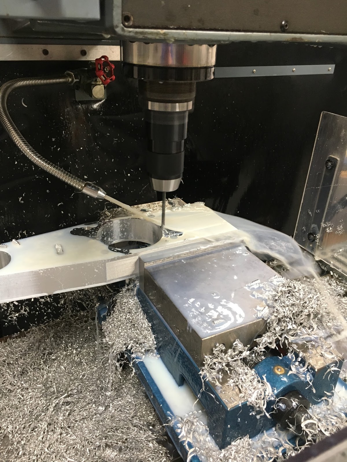
Things were now on a roll. Out came the drills - 10mm:
5.5mm:
....and 3.5mm:
and finally the chamfer mill:
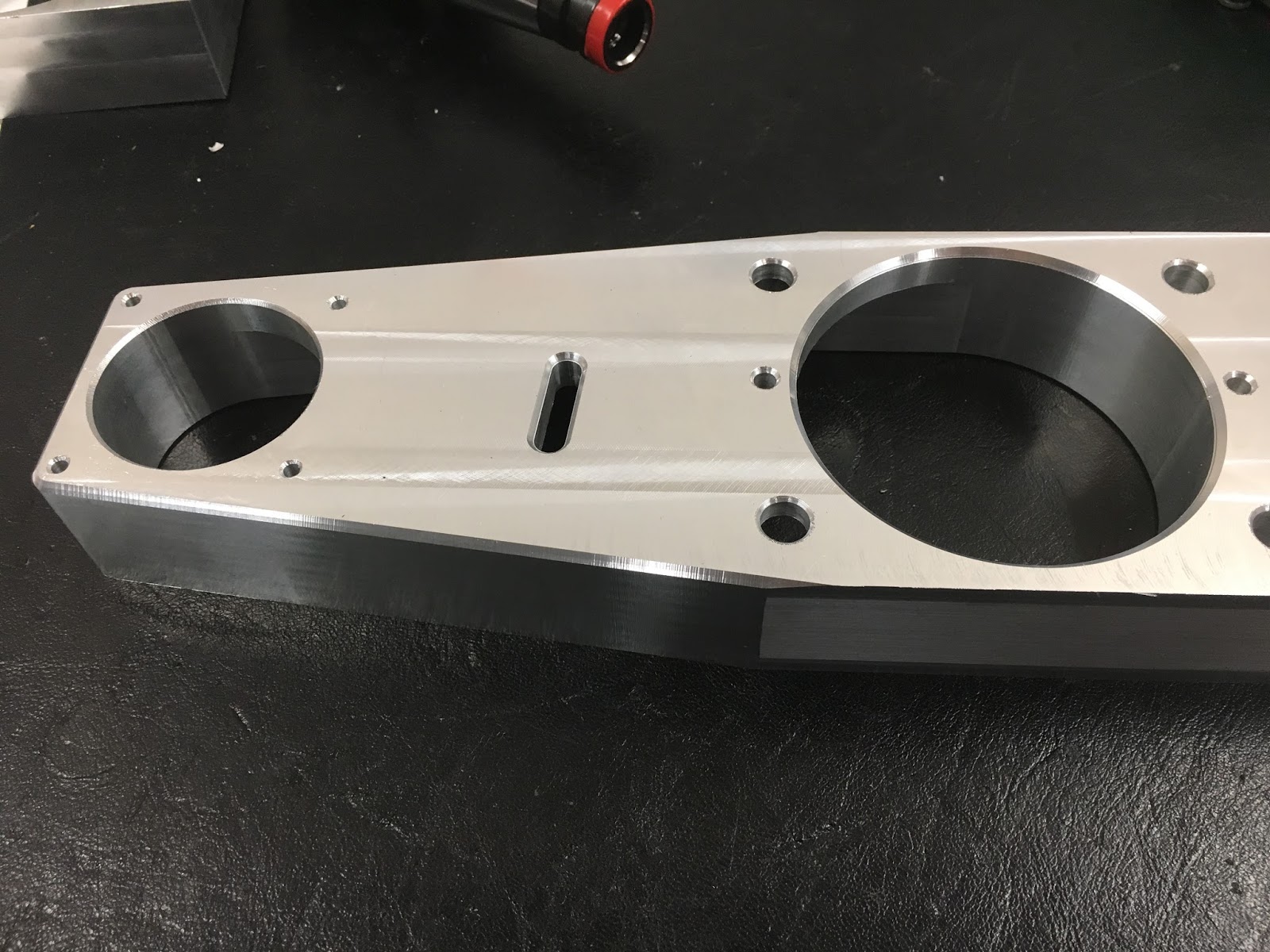
Final result:
Incredible. Job done, no breakages. Looks half decent. Observations:
The bore diameters were about 0.25mm undersize. Yet the cutter is bang on 10mm. Not sure what this was caused by - possibly I should have opted to select a final "spring" pass (I think there's a check box for that). I need to look into this...
The edge of the chamfers had a slight burr thrown up. I suspect the feedrate is too low, so I'm almost rubbing rather than cutting.
As noted, chip recutting is a problem when ramping into material or opening out a closed cavity. So in a piece like this one, it would make sense to put a hole through the stock with a large drill before starting to mill. Then there would be somewhere for the chips to drain away.
The coolant system needs to be improved. If possible, I'd like the chips to be blown clear, although this is a messy, wet business. It probably requires some shower curtains as well as a better nozzle system.
Now to turn the work upside down and prepare for the final 8 operations....