Sunday 28 November 2021

Hard machining some Multifix toolholders

What up?

I bought a mixed set of toolholders when I coughed up for a Multifix toolholder clone a few years back. 

These were bought from Create Tools who appear to actually manufacture some or all of the components. It's never clear if that's actually the case with many of these Chinese companies however, it's obvious that many of the companies selling them on are simply trading companies, no matter how hard they work at pretending they make them themselves.

Having not actually used the things, I stupidly included 2 of the boring bar holders AH2085, rather than specifying them all as AD2090 which have the simple rectangular slot.

Problem is that none of my boring bars require the trough feature, as in fact they all have a flat base. 

And?

This issue clearly requires remediation - by way of machining. It looks to me as if I should be able to open the slots out to take a std 20mm x 20mm tool. This sketch sort of helps to explain what I mean - if you can understand it. I've simply superimposed the 2 profiles and it's shown as I would mount a toolholder in the machine ie "slot up".

It would look like this in the flesh:

Sounds simple enough. But hold on, this thing is (should be) hardened. No problem if I'm using carbide tooling and don't get carried away on the speeds and feeds front. But what are we dealing with here?

Tough talk:

Luckily I have a Leeb hardness tester that may give me some idea. Although these aren't deadly accurate, they are a bit more elegant than running a file across the surface. The principle of operation is observing the coefficient of restitution of a ball bearing fired at the surface. By listening to the multiple bounces, it's possible to make a half accurate estimate of hardness. 

Here's what I found - around 20-30HRC, which is indeed harder than mild steel or tempered tool steel. So I will need to take my time and be prepared for some sparks.


I couldn't decide initially whether to use CNC / CAM to machine these 2 holders. Either way, it seemed sensible to get a feel for recommended settings. To my understanding, you should run almost as fast as you can (surface speed) and take fairly light cuts (feed per tooth). 

Let's have a look at some hard milling F&S starting values and take it from there.

Let's get cracking:

Yes, I couldn't see the point in programming this up when I could simply feed the tool manually with the MPG. It's a simple matter to calculate the coordinates for the tool, so manual feed it is.


Job done. Now some tidying up with diamond needle files and Bob's your auntie.


Looks good to me. 

Good. Now I can make better use of the toolholders without needing to swap tools endlessly, which rather defeats the point of having quick change tooling....

Saturday 6 November 2021

CNC Bantam - containing the chips and coolant

The recent trials have gone well and I seem to have a functional CNC lathe on my hands. However, the swarf coming off the work is hot and gets flung far and wide. The cross slide extension piece machining has left nasty blue ribbons all over the shop, literally. Time to think about the next steps in the lathe conversion ie refitting the various chip guards etc.

On the std machine, the rear splash guard (7) simply clips on the back of the chip tray and is supported at its top by a "splash guard extension piece" (8) that hangs off the headstock.

As I've pimped up my machine with a larger (3kW) motor, the splash guard extension piece will need to be spaced away from the rear of the motor if it's going to be able to draw any cooling air into its fan. That will require me to do some simple sheet metalwork. The main splash guard itself can simply slide along the chip tray, so no work is needed in it.

Positioned something like this mockup. The new gap is clearly visible - about 20mm or so:


There we go. Bit of loominum and some pop rivets and Bob's your auntie.


That's only a part of the solution though. I'm going to need something at the front and top too, as chips were being thrown in all directions. Some sort of "up and over" cover perhaps? Note that few (none?) of the various control knobs have any purpose now, so access to those really isn't going to be necessary

Off with the knob:

Of course, having spent the last week or so designing and machining up the cross slide handwheel extension with the precise intent to enable me to reconnect the micrometer handwheel, it now looks as if it's one of the few things preventing me from fitting a full frontal shield that would drop down over the chip tray. Besides, it has little purpose on a CNC machine other than making the machine appear to have a mind of its own. And it was a nice test piece for checking out the new CNC features.

I'm now going to jettison the handwheel and the nosepiece it is mounted on (bizarrely described as a "keep" in the parts list - go figure). When I'm at it, I'll also remove the selector lever from the front of the screwcutting gearbox. As well as being obsolete, it's the only other feature that protrudes where a front screen would need space. I'll simply remove it and its friends and keep them in a bag with the other stuff I've stripped off.

Sorted. I will need to make up a bung to keep shit out of the gearbox at some stage. Tissue will have to do for now...


Looking up the bed, it's clear there's a bit more room to play with here:

Obvs the cross slide will still overhang the saddle somewhat when it's at G28 / full retract but at least there's no pointless handwheel sticking out. I can now imagine a splashguard at the front of the machine (hinged at its base?), up to the height of the bed ways. And a (rear hinged?) top guard that drops down to meet it, perhaps.

I've got some of that corrugated polycarbonate sheet material, so I can make up a (hopefully) workable arrangement. If that looks good, I can get myself some clear polycarbonate sheet. One step at a time....

Splining the cross slide ballscrew extension on The Shiz

Colchester splines
Having turned up and threaded the body for the extension piece with undue cockup, I need to spline the thing so that the handwheel will fit on it. The scheme used on the Colchester lathes has 6 splines, with parallel faces on each side of the raised spline section. Words don't describe that easily but a sketch view does a good job. 

This is the same spline standard used on the change gears on the screwcutting drive train - I came across this when I made my still-born single tooth screwcutting clutch, which was an adaptation of Graham Meek's concept. I milled these manually back then and it didn't seem to be very difficult once it was all measured up carefully.

Here's what it looks like:


It's fairly easy to create this in a sketch, then create a circular pattern:


How to machine this?
At this point I could go mental and try to generate a fancy curved (cylindrical) surface between the splines using some sort of simultaneous 4th axis moves. Or I could if that toolpath were available in my version of Fusion. Which it isn't, as I can't justify spending £200/month on those blasted "extensions" of theirs. 

Instead I will use indexed ("wrapped") toolpaths to do the job. There's no problem taking more material off than strictly required if that makes the job easier / possible.

My plan is fairly simple. Using a 4mm end mill (which is spot on for the gap between splines), 
I will machine one side of a spine tooth...


....then the other side....


....then remove the material between the troughs created:


The overall collection of toolpaths looks like this:


Chip time:
I've finessed the feeds and speeds, set the heights, checked for unauthorised moves and looked for any other gotchas. Now the time has come to stop fannying about and cut the fucker.

I currently have a Tool 8 which is a 4mm 3 flute carbide end mill but technically it's an uncoated (ie loominum cutting) tool. However, I'm talking low carbon, mild steel here and will be taking light cuts (10um per tooth) with a shallow depth of cut (just over 1mm), so I doubt it's an issue. Besides, it's a Chinesium cutter from Yuze Tools, so it didn't cost a whole bundle and this is a good chance to try them out on steel for the first time.


Perhaps a cleanup might be in order before I get machining? Poor thing has been buried under a load or loominum and polycarbonate swarf. That won't do.
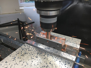

Off we go:
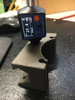
The WCS origin for this setup is on the end face of the splines, on the stock axis - for 4th axis work it certainly needs to be on the axis of rotation. I can probe the diameter and end face easily enough in X and Y with the Renishaw probe, then pick up the outer diameter of the stock to determine / set the Z axis position.


That worked out nicely. The runout is about 2''' on the "Kurt" DTI - that's about 50um which is pretty good for the 3 jaw chuck in my 4th axis and for what I'm doing here it's more than good enough. I'm fitting a handwheel on a shaft, FFS.


Right, enough dicking about. Z ref height set and tool length checked for Tool 8. Off we go - what go possibly go wrong etc etc. 


And here's the video evidence:


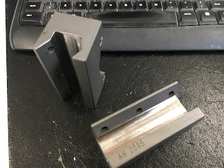
I should have gone for the Youtube Warrior cunning stunt ie trying the handwheel live immediately after the machine had finished, 'cos it fitted straight on. Bloody hell. Here it is in its glory:


Alongside its predecessor:


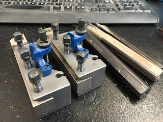
Ready to go on the machine:


Well - does it fit, Fatty?
There's only one way to find out - and there's no time like the present. Here's the old, temporary assembly coming off:


I'll stash the old leadscrew and splined shaft in the cupboard along with the other manual controls I've removed. There may be some value in having all that shite if somebody takes this off my hands for another few decades when I'm done with it.


And here it is - and yes, it all works. 


Bloody hell, I think we can call it there.

Tuesday 2 November 2021

Let's make something real on the CNC Bantam!

Surely not?
Well I seem to have a working-ish CNC lathe on my hands finally. So let's get busy and show (if) it actually works. 

Currently I have a plastic wheel that was liberated from the Blidgeport quill feed when I converted it to CNC. It looks shite but a pukka replacement would have required a fair bit of manual turning along with some spline milling. My plan was to eventually replace the temporary plastic handwheel on the cross slide (sorry - "Z axis") with the original micrometer dial. And what better a test piece to make on the CNC lathe - "physician heal thyself" and all that.

The job comes in 2 phases - firstly turn up the spindle itself, then over to The Shiz to machine the splines for the micrometer handwheel.

CAD and CAM for redesigned shaft:
Here's the original assembly I'd designed for the conversion. It would have retained the original power crossfeed drive pinion and would have required the ballscrew extension to extend through its centre, along with a small diameter splined section.

As I no longer plan to refit the apron and don't need the original drive pinion, I can simplify the ballscrew extension like the following. It's pretty simple, apart from the spline which I can't avoid if I plan to retain the nice micrometer dial handle.

I have some ~28mm mystery metal that looks suitable for the job. It has rusted slightly, which suggests it's some form of mild steel at least. Let's set it up as the stock in Fusion and create the toolpaths.

Here's the roughing and finishing operation for the "back" end of the part:

And the roughing, finishing and threading operation for the "front" end of the part

Right, here is the beast in its current glory:

Tool setup. First, get the tool height(s) set up:

Then do the touchoff operation, to avoid a bad experience when the tool needs to be changed from tool T4 (roughing / finishing) to tool T6 (threading). It's different to a mill although you still need to issue a G43 at some stage. However, the gmoccapy GUI buttons seem to handle the touchoff including the tool changeover. 

If in doubt, a T4 M6 does the tool change and a G43 T4 handles the tool length offset. And as it was my first time with this GUI, I did copious sanity checks to ensure the tool offsets etc were being handled correctly...

Off we go:
First stage roughing and finishing looks good to me. Of course, the finish tends to be better when you take a decent cut with carbide tooling, so the "finish" skim resulted in a rougher finish. Perhaps I should have used a ground insert for these light / finishing cuts but it's still fine.


And my god, the M12 thread has come out nicely - my first threading in steel:

It looks as if it should fit and function:

Now to flip it around and machine up the other side:

Light cuts because it's fairly slender and has a long overhang.

Came out nicely.

Alongside the leadscrew / splined drive shaft it replaces:

Looks good to me. Now over to The Shiz (via Fusion 360) for spline machining....

Final assembly and test of the spindle nose adaptor - RESULT!!

After the recent distraction caused by the 3D scanner, resurrecting the 3D printer and buggering about with the throttle bodies for my Honda...