Sunday 12 February 2023

Making the cams - Pt1

The cams need to be hardened, so the EN9T I bought recently should do the trick. This is like 1045 carbon steel ie can be hardened and tempered without any exotic processes being required.


I need a 19mm diameter but naturally I bought 20mm so I'll need to turn it down and this stuff isn't the nicest material to machine.


I just need to turn it down to 19mm, create a 3mm width groove, chamfer the edges and part it off.


There you go. Some deburring will be required before it will slide into the bore. Otherwise they came out nicely.


Now I need to machine the eccentric cam. The eccentricity is 0.8mm. How to machine this? There won't be much stickout on the lathe, so I'll drill a centre hole in The Shiz and bring up the tailstock.


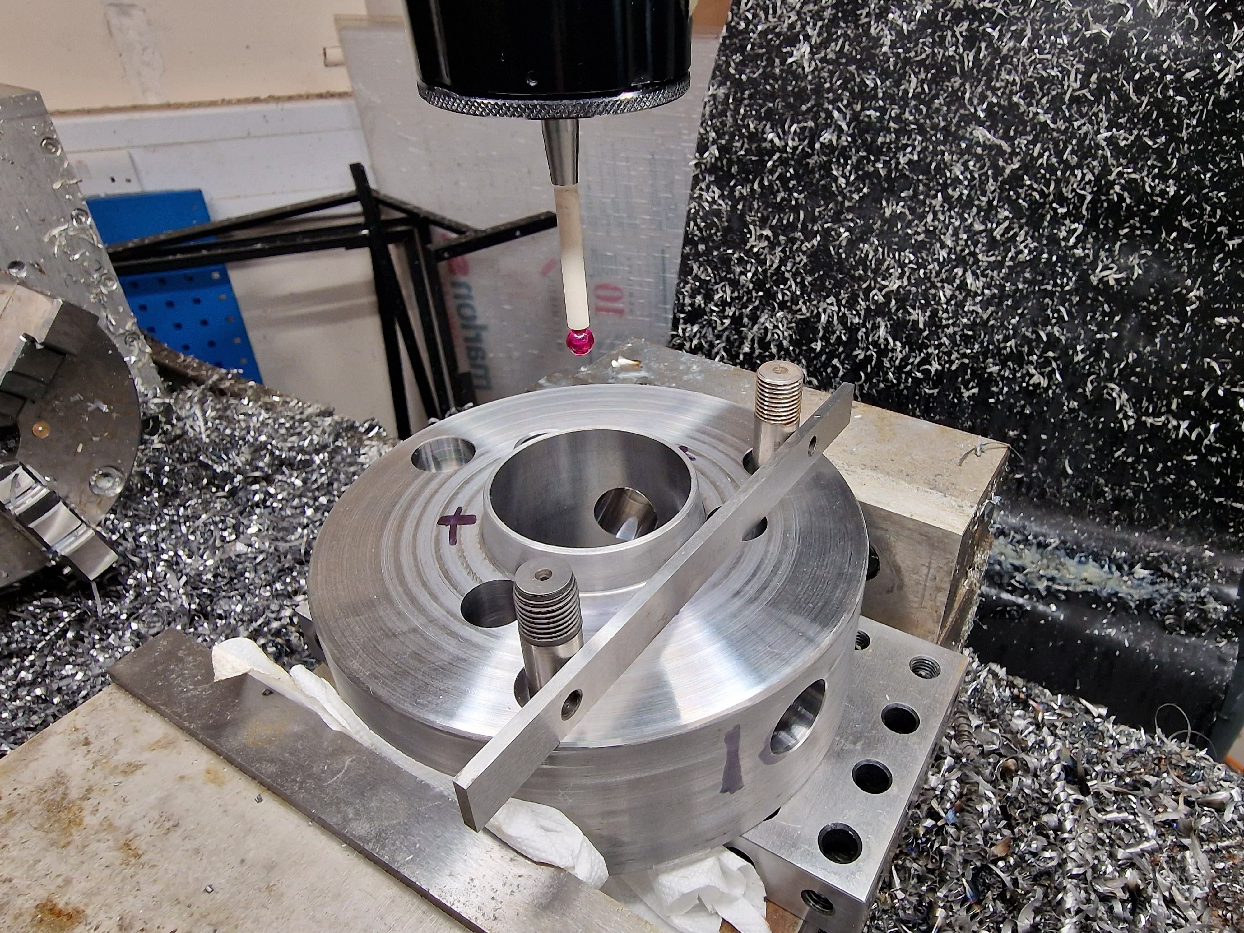
I can find the centre using the Renishaw probe, then move the table to create the 0.8mm offset and then drill the centre hole.


Like this:


To set the blank up in the 4-jaw with the centre hole on axis, the simplest method is to use a centre and DTI. Once the runout is dialled out, the part is on centre.


The Tree has a hydraulic tailstock. You can set the preload using a adjustable pressure regulator in the valve block. The existing setting seems to work OK without driving the blank into the chuck!


It's going to be a bit tight in there....


Nearly there. Just need to clean up the shoulder with a parting / grooving tool.


That worked out OK. The final measurements are spot on.


I'm now out of time today but here's the second part set up and ready to machine.

Friday 10 February 2023

Bollocks. Stupidly, I let The Stupid Fat Bloke set up the part in The Shiz and program the drilling / boring operations using dimensions from the 2D Drawing. 


Nice work, Fat Boy. But before you drill those radial holes, any blind idiot can see that the camlock stud bores are in the wrong place, by exactly 60 degrees. Apart from the fact it doesn't look like the 2D drawing, it's obvious that the fixing holes would clash with any radial cam bores. Dickhead.

But all is not yet lost, thankfully. The answer is to create another 3 holes for the cam studs, resulting in a total of 6. Three of them will stand as testament to the power of idiocy. These won't be so obvious when the chuck is fitted but the only alternative would be to start again and make another body from stock. Seems the path of least waste that my laziness will appreciate.

So firstly I will carry out the radial drilling / boring operation in the 4th axis, before replacing the thing in the vise and drilling / boring the additional 3 axial holes.

Initial step will be to (carefully) set up the work for the 3 radial bores. Luckily I'd set up the 4th axis during the last session, so apart from double checking, there's not a lot of actual, setup to do.


Off we go. However, I soon determined that my scepticism about the Indian 3-jaw chuck having enough grip to withstand the drilling forces required to force a 12mm drill through were justified. Never mind - this block of loominum can hold it in place against the jaws.


Nice finish from the boring bar.


Needs to plunge about 43mm which still leaves about 10-15mm clearanc.


Now back to the horizontal setup. How to align the holes? Actually, the Centroid software allows you to use CSR ("coordinate system rotation") to reorientate the machine axes to a measured direction that is picked up by to probed points. In this case, I've got  couple of tight fitting 12mm end mills and a straight edge. The Y axis will then be aligned to these 2 holes that are intended to be on the same Y coordinate.


With that done and some sanity check probing on the existing hole positions, I can get drilling and boring again.


That's the 12mm holes drilled.


...and bored


But - does it fit? Yes:


The cam studs are visible in the radial bores. They look about right.


Looks pretty good, if you ignore the 3 idiot holes:


Cool - I should be happy with that. Next I need to focus on the cam studs...

Sunday 5 February 2023

Boring the axial holes

How did that work out? 

Here's the drawing and table from the ISO standard:


I guess I'll need to do a decent inspection of the critical dims but without getting too carried away here, it's clear the part is still slightly oversized as intended where it matters. I need to leave some metal so that I can finish machine it in position once the rest of the maching has been done (cross bores etc).

Let's continue with the machining:

Now for the various axial and radial bores. There are 10 of them on this part:

  • 3 mounting holes for 7/8" UNC cap head bolts (12mm through bore, with 17mm counterbore) - to mount it onto the A2-5 spindle nose.
  • 3 through bores (15.1mm) - for the D1-3 pull studs.
  • 3 radial bores for the D1-3 cams (19mm).
  • ...and 1 blind bore for the drive pin on the rear of the body (15.9mm).


Over onto The Shiz. First, probe the centre of the bore, which I will use as the datum in X and Y.


Now I need a 12mm drill for the fixings holes and as the starting bore for the stud holes. I have a nice Osborn (RS) HHSCo drill - but the tips are fucked. Some clot has "blunted" them previously. Out with the Drill Doctor thing:


AS before, I'm somewhat underwhelmed with the surface finish this thing achieves. The diamond wheel needs more diamonds ie smaller and with a higher density. Consequently, it looks as if somebody had sharpened the thing by scraping it against a wall. But at least the geometry seems to be fairly close.


Simplest thing here is to simply position the drill using X and Y coordinates in MDI and then manually feed the drill with the wireless MPG. So a 2D drawing is helpful here:


Off we go again:


Next, I need to use my Chinesium boring head for the first time. Certainly looks the part but is it any good? Only one way to find out....


It's just long enough to bore through without hitting the tapered register:


Bloody hell, that's not bad:


The bores seem to be in the right place. This 3 jaw fits nicely, although of course I haven't finish machined the register yet, so it doesn't fit against the flat surface. Good result!


Now to counterbore the fixings. I went from 12mm to 17mm in 2 steps and the tool handled it without any problems or chatter:


Trial fit shows the cap head bolts fits nicely:


Good. Now I need to think about how to drill the radial holes. The actual machining is simple enough with my 4th axis device - but picking up the datum angle may need some careful thought and work.

Final assembly and test of the spindle nose adaptor - RESULT!!

After the recent distraction caused by the 3D scanner, resurrecting the 3D printer and buggering about with the throttle bodies for my Honda...