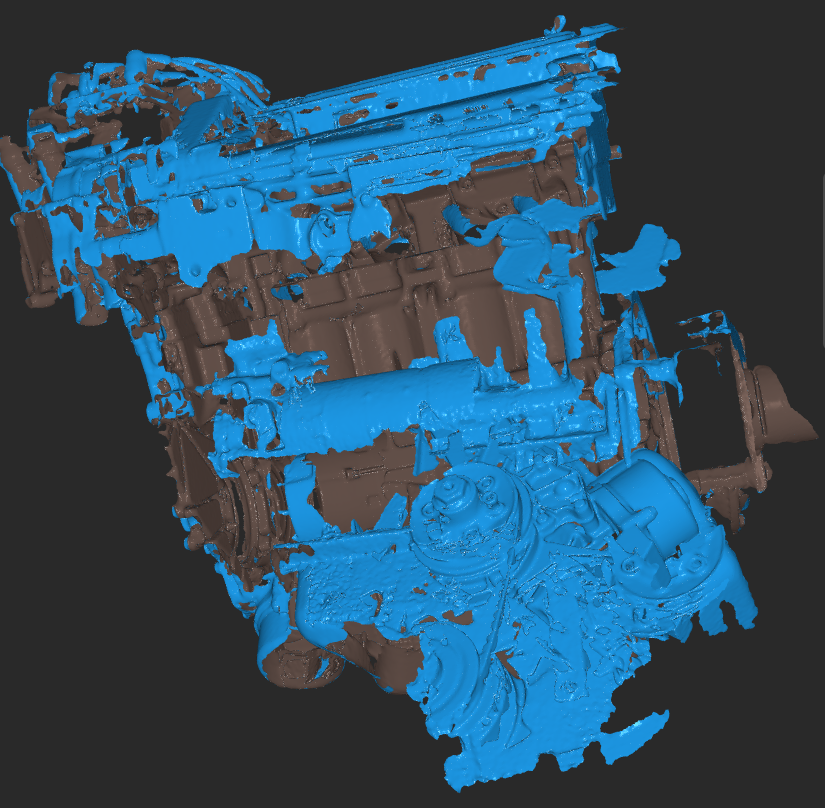
Having played with the 3D scanner and dismissed this as a sensible means of "designing" stuff, I'm going to focus on CAD solutions for connecting up the throttle bodies and crafting some sort of airbox solution for this setup.
Here's the current arrangement - the throttle bodies (ITBs) are only loosely held in place here on the S800 intake manifold, to illustrate the general concept:

I've previously hacked off the bottom of the original CBR600RR airbox, "leaving for later" the question of how to close it up again. The original airbox fouled the alternator.

The secondary injector bank sits in front of the intake trumpets. They only come on at high engine speeds and throttle settings.


It's ages since I last fiddled with this setup. Back then, my solution to matching the ITBs to the engine were these aluminium adaptors. They are needed because the engine ports are slightly Siamesed in pairs.

Each pair of ports (1 and 2, 3 and 4) are on 65mm centres. But overall, the ports on the engine are spaced such that the average spacing across the 4 cylinders is 74mm, which is rather handy given that the CBR600RR ITBs have a consistent spacing of.....74mm across all 4 ports. If you do the math, that means each inlet in a Siamesed pair requires a 4.5mm offset.
I went with this hooky solution because it was the best I could do back then. These were made by clamping some thick wall aluminium pipe eccentrically by 2.25mm in the 4 jaw, then machining each end (manually). Ideally, the porting would be flowed to avoid sudden discontinuities. I had imagined that I would do this manually at some later date using a hand held burr.


The inlet ports are somewhat less than free flowing with those steps at the transitions:

Here's what I plan instead. The rubber adaptors are looking a bit perished after 46 years, so it may be rather foolish to design around them. Instead, I will mount my new adaptors direct to the water cooled inlet manifold. This means the mounting surface could see ~100C which is a bit hot for most 3D printed materials. However, the solution may simply be to make a heat insulator plate from Acetal / PEEK or similar. I can deal with that later.

Using the Loft function, I can sort of align the inlet and outlet so they transition more smoothly.

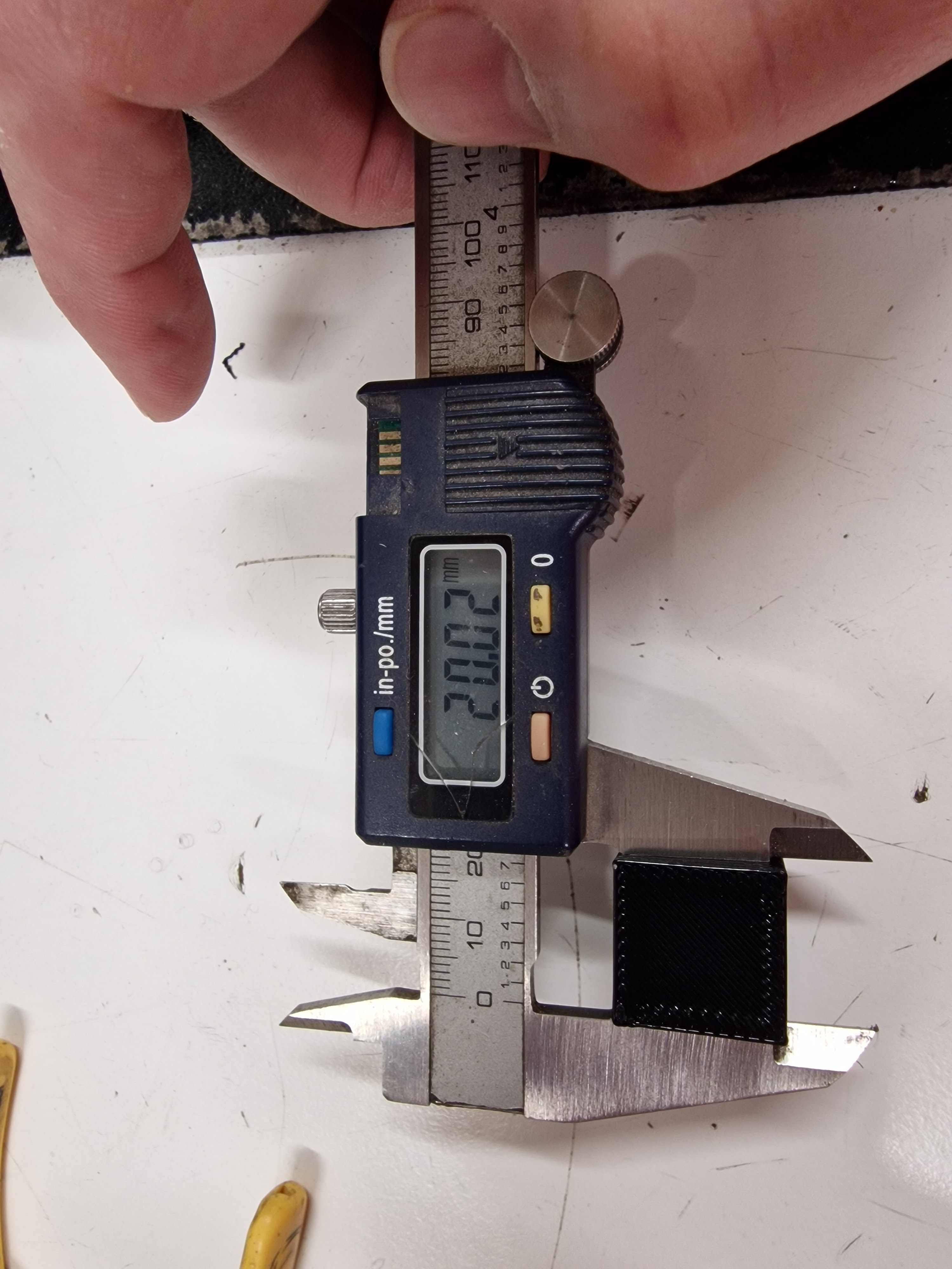
Let's try out the idea in PLA. Obvs I won't be using PLA on a real (hot) engine with gasoline but this should give me an idea if the concept is workable. I'd probably get them made by one of the online providers using something more sensible like glass filled PETG or perhaps some sort of SLA material.

The weak point will be the relatively narrow (thin) neck that mates with the rubber connector at the back of the ITBs. One solution might be to make a short metal insert that fits into the plastic body - but this would require some new materials that I don't currently have and some machining thereof.