Friday 27 April 2018

Drilling, tapping and slotting the bracket - job done!!

The final operations are relatively simple, although obviously there is the possibility of scrapping the part. I need to drill and tap the holes for the DRO and limit switch brackets, then form the slot that provides the "spring" in the yoke and allows me to clamp it to the ballnut. 

I'll simply drill and tap the holes on the Blidgeport using the DRO.


For the 3mm slot, I've ordered a couple of tiny 3mm end mills. These are tiny, biddy versions of the 12mm cutter that performed so well on the main operations. 


Here's the Cutwel page for the family of EMC85 cutters. And the cutting data.


Set up a toolholder and defined the cutter geometry etc in the tool library:


And the feeds and speeds:


It has a 6mm shaft, so will fit a std end mill holder. And like the bigger version, it has a reduced shank so that it will reach down into a slot - up to 12mm from the shoulder. I need just over 11mm (!!).


Struggled a bit with the CAM, as expected. Wasted a fair bit of time trying to define a piece of stock that would fill in the modelled stock body. In the end, I found that using the 2D Contour path with ONE of the slot edges selected worked fine. And using the heights selection, I was able to limit the bottom height to just below the large bolt hole through the body. So I have one operation from the top...


....and one from the bottom.


The entry and exit paths have to be considered. I didn't want them tracing all sorts of fancy loops and curves on the way in and out. 


Notice the distances and radii in the linking tab. They control the flight of the tool around the entry / exit and how far the tool moves beyond the feed distance before moving to the next pass:


...and the "tangential fragment" distance in the "passes" tab. This controls the extension of the toolpath out to the right of the part:


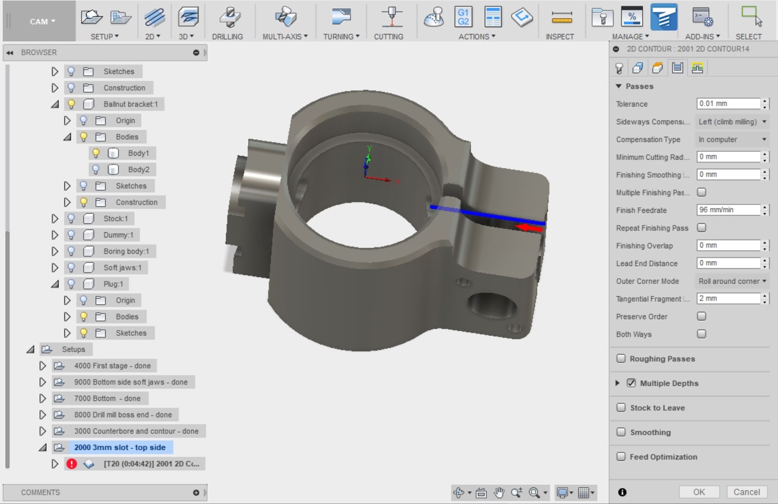
Apart from deciding how brave I feel about the final feeds and speeds I should use, that seem to be all I need to do. Currently I have 2mm roughing stepdowns and 1mm optimal load, plus 0.004mm per tooth. I may dial that back, particularly the stepdown.


Hiatus:


Despite ordering the baby end mills on Wednesday morning, the "First Class" service from The Royal Mail has been a long way short of that. There was a time when First Class would mean next day delivery. It's now Saturday, the postie has been - yet still no end mills. Grrrr.


Drilling and tapping:


Finished drilling through the 10.5mm clearance hole for the pinch bolt and the 3.3mm tapping holes for the four M4 holes (DRO and limit switch bracket). Then machine tapped those five holes for the first 5-10mm to ensure they were straight. Finally, finished the tapping by hand, off the machine. To tidy up, with the DRO homed in, I was able to lightly countersink / edge break the drilled and / or tapped holes.


M10 pinch bolt:


Made a nice job. But there again, I used the nominal tapping drills, so the thread should have been close to 100%:


M4 screws:


Slotting the yoke:

Sod it. I couldn't be arsed to wait for the end mills. Besides, there's a pretty good chance the yoke will spring together when I finally break through completely and the cutter will ping. So instead, I bolted a machine vise to the bandsaw and made 2 cuts. 

The moving jaw on these Taiwanese saws just bolts on to the nut:


Low tech stuff - simple but well proven:


Ready to go:


Looking good:


Making the second cut (the slot was "designed" to be 3mm wide):


Funnily enough, there was no spring either way when the saw broke through. Needn't have worried.


It's probably not dead on in terms of alignment but it certainly looks pretty darned close. And for the application it will be fine.


A bit of deburring and tidying up with some diamond files and a diamond plate and - job done!!


You can see a slight cockup in this first photo. I placed one of the holes on the wrong side of the bracket. Managed to realise that before drilling the second matching hole. It'll be hidden by the bracket. Besides, it's good to show that I am human and thus fallible:


This is my "good side": 


Alongside its hand made aluminium twin:


There.

Wednesday 25 April 2018

Boss end operations

Fnaaaar. Nothing to do with the old todger. The bottom side is complete, so now to focus on the side that interfaces with the quill.

There's a (horizontal) cylindrical boss that mates with a locating counterbore on the quill and a (vertical) cylindrical face that sits against the external face of said quill. Then there is a rectangular section that reaches through the long slot in the head casting and connects the main yoke / bracket body to the quill. I need to finish off those features which are currently only roughed out.


  1. Drill pilot hole 7mm through centre of boss.
  2. Drill 9.5mm using 3/8" carbide end mill (don't have a drill that size that's fit to use).
  3. 2D Circular with 3mm (actually 1/8") ball end mill to form the clearance channel around the boss. Had to change the channel in the CAD model from circular section to square to fit the toolpath.
  4. 2D Contour to machine the 2 steps and fillet radii. I've got round to adding the fillets on the top end of the rectangular island (see below).
These are the 4 paths, ready to go:


Now need to set up the 3 tools:

  • Tool 5: 1/8" ball end mill in ER16 collet chuck, 60mm gauge length.
  • Tool 13: 3/8" carbide end mill in ER40 collet chuck, 70mm gauge length
  • Tool 14: 7mm HSSCo drill in ER16 collet chuck, 60mm gauge length

Got them set up in the Acorn tool library:


Now, set up tool length offsets....


Monday 23 April 2018

Quick soft jaws for 2nd operation / finishing off the bottom side

I need to flip the part over now and face off the extra stock. It's a complication that makes the creation of next set of toolpaths a bit tricky. It's arguable that I could hold the existing part between the "ends" but that looks very risky. If the part moved during facing, I'd ruin it and possibly the tool too. Instead I'll machine up some soft jaws. They won't be bolted to the vise which makes them quicker and easier to model up and machine.

Created some simple rectangular extrusions for the vise jaws that I have already made (and used for the Y axis housing). Then took the sketch for the main body extrusion and used it to cut extrude the jaws. Finally, created an extra sketch to remove any fine radius corners and sharp edges. I could have done this in the original sketch but overlooked it. This method worked. The jaws will be spaced apart during machining by some 19mm (3/4 inch) box section I have on the shelf.

Now I have the jaws modelled up, time to CAM the roughing and finishing operations. 2D Adaptive to rough out the cavities, then 2D Contour to clean them up.

Set up the G54 origin at front top left corner of the jaws with reference tool - no need for any fancy probing, as the exact position isn't critical in any of the 3 axes:


 Load up Tool 17 (10mm long series loominum cutter):


These cutters just love chomping (almost silently) through loominum:


Now load up the steel lump and prepare to face off 13mm from the top:


Here we go:


Almost there:


Sorted:


Now for chamfering the top edges and profiling the cylindrical face (at RHS of bracket in the above shot).


That's the bottom side finished.

Saving a partially machined part as a solid body

Saving the workpiece as a solid:

You can save the simulated workpiece as a solid and then import it back in, for use as a stock model for subsequent operations. You might argue that "rest machining" might accomplish that but I don't know if you'd be 100% right.

There have been a few Youtube vids showing how to do this. Here's one that is short and to the point. Slight issue here being that it didn't work for me. I suspect Autodesk have changed something. 


This is what worked for me:
  1. In CAM simulation, save the "finished" model as STL. Right click > Stock > Save stock. You don't seem to need to specify the file / model type.
  2. Change to the Fusion Model environment, import the STL by selecting Insert > Mesh. Rename ("Stock body" etc), as required. NB: Ideally, open a new file to do this - you must turn off the timeline for the "STL to BRep" option to appear in the Model environment.
  3. Reduce the size of the STL file (in the Mesh environment, Modify > Reduce). I reduced it to 0.05 (ie 5%) of original and it lost very little noticeable detail.
  4. Convert from STL to BREP: Modify > Mesh > STL to BRep. You now have a solid body.
  5. Import this new body into your working file from the Data Panel: "insert into current design".
  6. In the CAM environment, you can now select this body when specifying the stock for the next operations. 
Sounds simple enough but the struggle at this point is getting the toolpath to stick, not the stock model. I suspect I'm going to have to simplify the model by filling in holes etc. 

Sunday 22 April 2018

Cuttin' chips - main body - adaptive, profile and pencil toolpaths

Make some chips finally!

Sod it. After losing several days messing about with the Renishaw probe, I'm finally in a position to be able to machine this damned bracket. I done got me a damned fancy cutter and generated all the toolpaths. Although I have no guards and this will be messy, nobody will die if they get a bit of coolant and swarf on them, so off we go.

Face milling the top surface:

First face it off with the Korloy 50mm face mill. I did this dry at ~980rpm. Interestingly, the machine correctly selected low ratio and drove the motor at just shy of 6000rpm to do so. So it all seems to be doing what it was intended, although I must admit I couldn't have told you that was all working. I must have done something right.

The finish wasn't startlingly good but perhaps if I'd used either WD40 or flood it would have been a lot better. As it is, this is cold rolled steel (CRS), so the skins is probably a bit tough. Doesn't matter a great deal, as very little of this top surface will survive beyond the first few ops.


2D Adapive - roughing out the main body:

Then the big test of the (expensive) new cutter. Needn't have worried - it flew through the metal, producing a fine stream of clean chips. Was a little noisy to start with but there again I was pushing at bit given the state and vintage of my machine.


Cleaning up - 2D Contour:

Then the 2D Contour, to clean up the external profile. I have to say this came out really well. The only vague issue was a "chirping" that came when the 12mm cutter had to generate a 6mm radius fillet in 4 places. There wasn't much it could do about that - it's more down to lousy design and tool selection. I knew this would be a bit marginal but I didn't want to reduce the radius any further, yet I wanted to use the biggest (most rigid) tool I could get away with. The bottom line is - the final result is excellent.


Then chamfer the top circular edges. I created the CAM on the PC in the workshop, loaded the tool and ran the g code. Quick and easy.

Forming the fillet - pencil toolpath:

Finally, used a Pencil toolpath to clean up the fillet which was left with a stepped profile after the roughing op. I defined a 6mm ball end mill / holder etc, generated the g code and posted it.


Although technically the ball end mill is for loominum cutting, it was fine here. I simply dialled the speeds and feeds down a bit - 6000rpm and 600mm/min. Having said that, it didn't hang about! There was actually a nominal 0.5mm axial stock left by the 3D Adaptive, so in fact it took off a bit more than I'd expected - but only what it was programmed to do! Nice finish. No suggestion of a problem.


I think that's it for this particular setup. Now I will remove the workpiece and remount it for the next operations. I should save the current solid and use it as the stock for those.

Saving the workpiece as a solid:

You can save the simulated workpiece as a solid and then import it back in, for use as a stock model for subsequent operations. You might argue that "rest machining" might accomplish that but I don't know if you'd be 100% right.

There have been a few Youtube vids showing how to do this. Here's one that is short and to the point. Slight issue here being that it didn't work for me. I suspect Autodesk have changed something. 


This is what worked for me:

  1. In CAM simulation, save the "finished" model as STL. Right click > Stock > Save stock. You don't seem to need to specify the file / model type.
  2. Change to the Fusion Model environment, import the STL by selecting Insert > Mesh. Rename ("Stock body" etc), as required. NB: Ideally, open a new file to do this - you must turn off the timeline for the "STL to BRep" option to appear in the Model environment.
  3. Reduce the size of the STL file (in the Mesh environment, Modify > Reduce). I reduced it to 0.05 (ie 5%) of original and it lost very little noticeable detail.
  4. Convert from STL to BREP: Modify > Mesh > STL to BRep. You now have a solid body.
  5. Import this new body into your working file from the Data Panel: "insert into current design".
  6. In the CAM environment, you can now select this body when specifying the stock for the next operations. 


Friday 20 April 2018

Shorter toolholder for Renishaw probe

Don't talk, just do it.

Finished setting up the toolholder in the lathe. Then parted off the collet body and skimmed over the resulting face.


Parting off the collet body:


Done:


Facing it off:


Making a chamfered hole for the 16m ball bearing:


Fits nicely - but sticking out too far.


At this point, I dug out the dimensions for the Renishaw MP1 probe. Seems my measurement of 52.5mm PCD was spot on.


Some quick calcs. I planned to use a larger ball bearing, 'cos the collet chuck has a 6-7mm bore meaning that the original 8mm ball won't work so well. I have some 16mm balls, so thought I'd enlarge the central socket to suit. Here is a sketch that illustrates the requirement:


Seems I should aim for about 4.2mm stickout from the face of the toolholder body.


But the body is still rock hard, probably the best part of HRC60, so not much danger of drilling it as it stands. So let's give it some heat to soften it up. If I can get it to red heat and then let it cool down, I should be in with a better chance of drilling and tapping it. Perhaps I should have done this before machining the collet body off but it was a bit of fun.


I have a load of propane cylinders from our camping days, so no problem on the heat front.


That worked nicely. It now drills like a dream with my HSSCo stubby drills. Drilled and tapped the M4 on the 52.5mm PCD.


At this point I noticed that I'd screwed up. The central bore is eccentric. That's what happens when you decide to take a 16mm ball ended end mill to the bore in a rush of blood. It results in a beautiful socket for the ball but unless you are more careful than I was, you end up messing up the job. Dick head.


Apart from that detail, it seems to be coming along nicely:


Cockup!!


Hmm. Slight logistical issue - the probe body needs to clear the drive dogs that extend beyond the flange when engaged. In particular, one of them extends about 20mm from the gauge surface so that the toolholder can't engage with the drawbar threads before the dogs are aligned. Things could get messy otherwise - insert the toolholder (not aligned with the dog), engage the impact drive and crash the dogs into the side of the holder. Not recommended.


Change of plan - need to either start again with another toolholder (I can forget that, as I don't have one) or weld a plate on the front (messy, lots of work and I don't have a suitable piece). Or mill a couple of clearance slots in the sides of the probe body? I favoured the latter, so that's what I did.


Machining clearance slots:

Seems a bit extreme to chew lumps out of a precision probe head but that's what is required and as long as I don't break through into anything critical, it will give me the neat solution I'm after.

I will have to remove the serial number label and the model lable on the opposite side. Managed to get them off with a scalpel. They are loominum, with double-sided tape to hold them in place.


This shows what is required - this is the longer of the 2 drive dogs but you can't be certain which way you will inert the tool, so both sides must clear it.


On the (manual) Bridgeport clone. It's a 12mm HSSCo slsot drill. The corners of the tool are a bit buggered so it doesn't cut very well. But I can't be arsed to change to a better tool. It will be good enough and I will debur it afterwards.


Done. Not the best bit of work I've ever done but it's fit for purpose, no cockups (this time) and it didn't break through into anything unexpected.


Dry fit looks OK:


Yes, I messed up the PCD holes. Third time lucky. The ball is seated in a 90 degree CSK hole, just like the hole in the probe body. It protrudes about 5.5mm from the face of the holder. That leaves the specified 3mm gap between the body and holder when assembled.


Finally assembled again. The complete probe assembly is now the same length as the original adaptor without the probe body. So now I have a probe that is over 2" shorter.


It's now much closer in length to the other normal tools. The Martest 3D indicator is the red thing - it's just too lon to be much use on this machine. Perhaps I should just fit it to a 30 taper toolholder and use it on the BP.


Heheh - job done. Last part - realign the probe again. It's rather like setting up work in a 4-jaw chuck:


It's better than 10um - probably about 5um.

There.

Final assembly and test of the spindle nose adaptor - RESULT!!

After the recent distraction caused by the 3D scanner, resurrecting the 3D printer and buggering about with the throttle bodies for my Honda...