Friday 29 March 2019

Align power feed for Bridgeport knee

What's this then?

Various shims, screws and a knob....


....a Z-specific bevel gear, bearing spacer, channel for limit switch end stops....


....the shaft extension, key and roll spring:


At least the thread is correct - I think it's 3/4" UNF


Drive unit fitted and shimmed, scale fitted:


Finally, cross drill 5mm for the roll pin. The steel is pretty soft and easy to drill.


You can see daylight through it:


There. All done on the drive bit.


Yes, it looks a bit odd, mounted at an angle like that but this appears to be how it is intended to be fitted. I believe the idea is to provide clearance for a similar power feed on the y axis although of course I don't have on here. I suppose I could have drilled and tapped new holes so that it would have been more rectilinear but there again it would have taken the operating knob lower down.

Now need to connect up the limit switches, power etc. But I had other stuff to do so it will have to wait for now...

Wednesday 27 March 2019

Finishing off the Z axis limit / home switch and DRO scale installation

Limit and home switches - and DRO head:

Here's how the limit switches and DRO scale were arranged. The limit switches are at either end of the square section loominum extrusion and the home switch is on the side near the top of it. I've selected the same fetching yellow / brown shading for the "target" as the switches to make it easier to spot here. These Omron switches are inductive (eddy current) proximity sensors which work with almost any metallic target. However, they are less sensitive to non-magnetic targets so I have deliberately chosen to make my target from a piece of loominum angle extrusion. This cunning stunt relies on the detection distance being consequently shorter, leading to a marginally(?) more accurate / consistent detection position. 


First, for no obvious reason, make up the bracket that locates the DRO reader head on the side of the yoke. I also need to make up some spacers to hold the DRO scale at the correct distance from the machine head. For this make up some spacers, using some nice mystery bronze or brass barstock:


Like this. I'll need to finesse the length later, so they are oversize for now.


The bracket goes in here between the reader head and the yoke:


And looks like this:


Or even better, like the top one in the next photo, otherwise I won't be able to get in to tighten the pinch bolt. There's plenty of movement on the DRO scale to accommodate a different position for the reader head, so this should work.


That'll do. Now drill some holes....


Getting there....


Pinch bolt in place. Looking good.


Make up some fatter spacers, as the originals didn't mate well with the DRO scale.


There you go:


Now over to the other side and fit the target piece for the 3 proximity switches. I put 2 diagonal holes in the yoke, one on either side of the pinch bolt to mount it on.


I've adjusted the target down a tad by bending it. Does the trick and reduces the distance between the home position and the +L (hard stop) switch. I want to lose as little Z axis movement as possible. It's about 2mm between the home position and +L limit switch operation.


Need to clean up the Leadshine stepper wiring and the switch wiring.


Take a note of the connections first:


It's not really the ideal wire to use (Cat5) but will have to do until I get something better.


Limit and home switches wired in properly through the cable glands, along with stepper connections:


Lid on.


I've done worse.


DRO in place and connected up: 


Controller configuration:
Set the parameters for homing: 


And the speed settings: 


Final component dimensions:


Then connected up the stepper drive error output to the controller. Stalling the motor or forcing it out of position results in this error message, which stops the machine. 


Knee power feed:
Next: Fit a motor feed to the knee. Knee mills aren't ideal for CNC conversion, as they have such limited Z axis movement. In turn this requires the knee to be set at the correct height to get best use of that movement. If you have about 100mm of travel (currently, in this setup), that has to cater for all your machining moves as well as any retract heights etc. These machines have a crank handle for raising and lowering the entire knee / saddle / table assembly but this can be pretty tedious work, with the risk of succumbing to terminal wanker's cramp. 

I removed my Align 500X power feed from the table when I converted to CNC. On the face of it, I should be able to re-use it on the knee, as the basic drive unit is the same. However, there are some additional parts needed to complete the conversion, namely an extension shaft and a different bevel drive gear. I was unable to find drawings for the shaft on the internet and even if I did, there would be several hours work involved, including an internal 3/4" UNF thread and an internal keyway.

Here are a couple of Pootube vids to show what is involved in fitting the factory knee power feed:


There's a local company offering the Align 500 Z-axis kit for £299 at the moment. Seems like a good price, as mostly these come in around £350 or more, even on ebay. There's one on its way, even as we speak....

Tuesday 19 March 2019

Z axis home and limit switches

My original assembly model in Solidworks had coloured components but since I imported it into Onshape and Fusion 360, most of those colours have defaulted back to vanilla settings. But you can see what I had in mind:


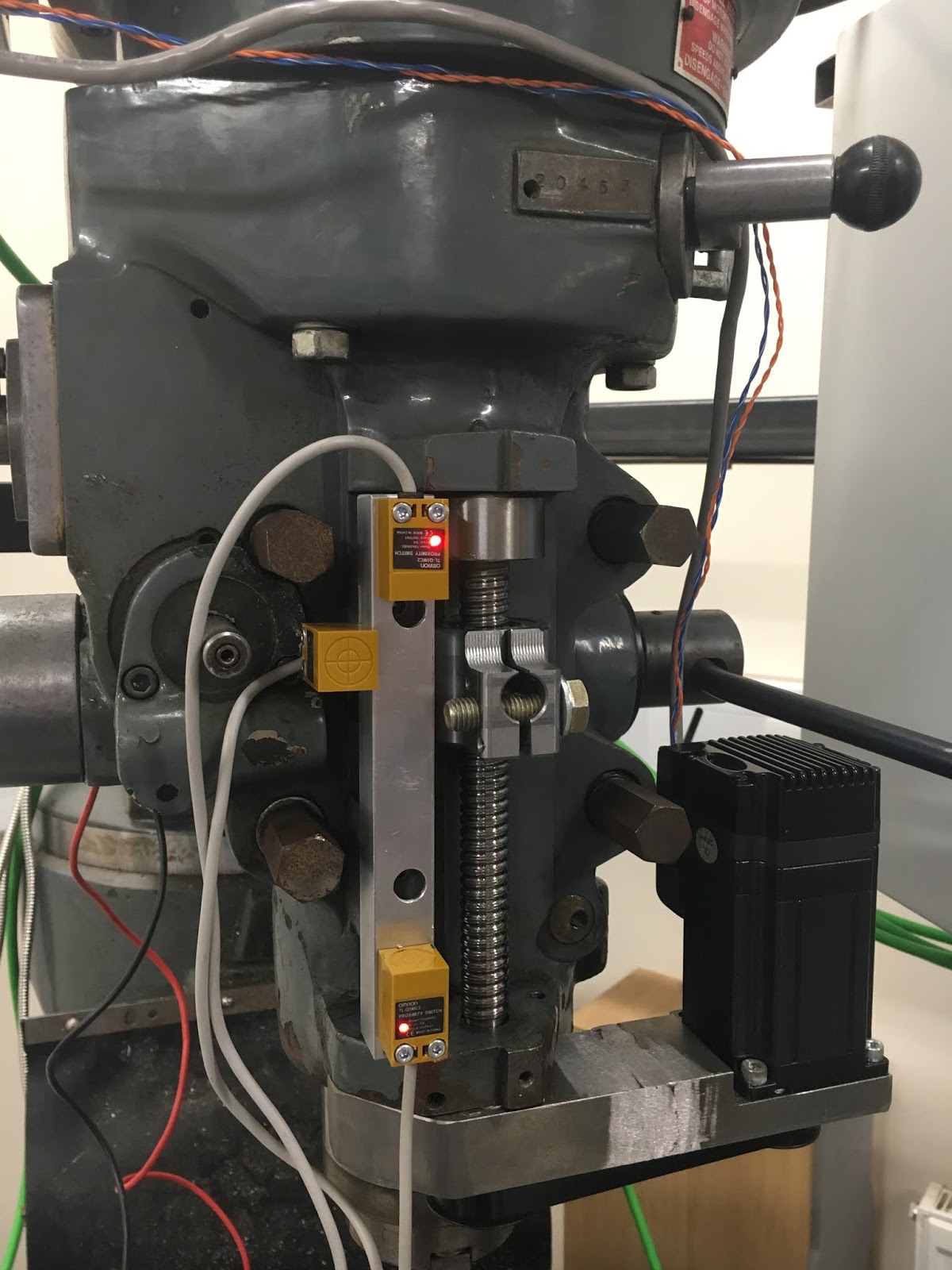
The 3 proximity switches are mounted on a piece of square section loominum, with slotted holes to allow for adjustment:


With a couple of holes for mounting to the head, using the fixings for the feed stop scale:


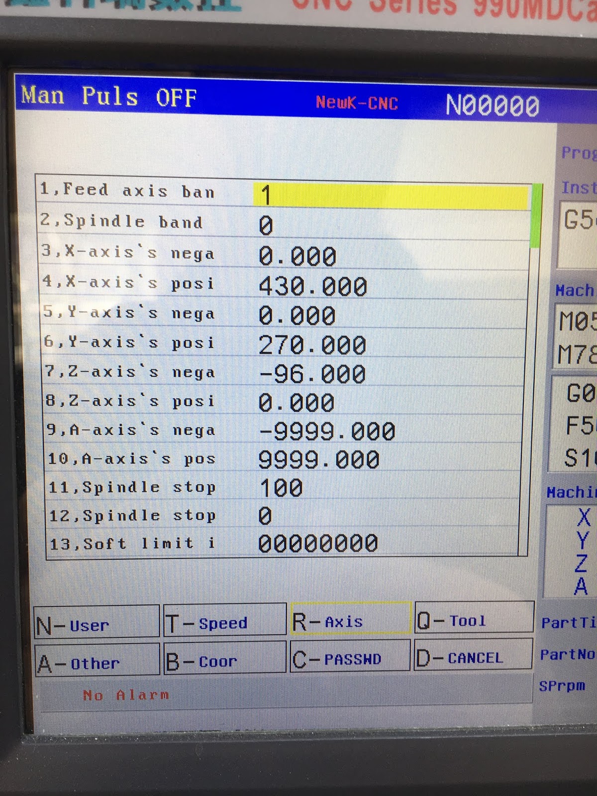
I have already connected up the junction box on the side of the head, so was able to quickly wire them up and test them out. The top and bottom switches are limit switches which haven't been wired to the controller inside the cabinet but the LEDs change state when a metallic target is encountered. The home switch is on the side and IS connected to the controller. Gratifyingly, that signal is shown on the diagnostics screen, so I've done something right there.


So I need to connect up the NC limit switches. All the +L limit switches are connected in series and all the -L limit switches are connected in series. You can't series up open collector switches that are running off the same power supply (the 24V supply for the controller) but in this case it's not an issue. I simply put the proximity switch at the bottom of the chain. 

The home switches were randomly defined as being NO, so it's simple enough to merely parallel up the open collector Z axis switch with the existing mechanical switches.

What is rather missing from the above assembly is the target component that rides on the yoke and triggers the various switches. I was certain I'd made this up but The Fat Stupid Bloke must have been busy in the workshop again and mislaid it somewhere. I'll make up another one and then stumble across the original.

There is also a bridge piece that connects the sliding head of the DRO scale on the other side of the yoke. Naturally that's missing too, although I found a partially completed 3D printed version. I suppose that might be a solution for the DRO head.

Final assembly and test of the spindle nose adaptor - RESULT!!

After the recent distraction caused by the 3D scanner, resurrecting the 3D printer and buggering about with the throttle bodies for my Honda...