Tuesday 30 May 2017

Back(lash) together again

I finally have the head back together again after removing the quill / spindle (several times), rebuilding the Z axis ballscrew assembly and refitting the top bracket with additional fixings. I haven't managed to eliminate the lost movement but at least I know what's going on now and how to improve it significantly.

I had to remove the Z axis ballscrew assembly to drop the quill / spindle assembly for inspection. It's not too much of a ball ache to do this but it does require the power drawbar assembly (including the drawbar itself) to be pulled aside There's a short extension piece that screws on to the top of the spindle (left hand thread!) and holds the drawbar captive. Unless it is removed, the quill assembly won't drop out of the drive splines. I think this extension is there to forcibly eject the bar if the toolholder is slightly stuck in the taper.

And given that I found the X and Y axis ball bearings needed to be replaced, I thought I might as well just strip the Z axis ballscrew assembly down and see what is going on while I was at it. I had no desire to remove the ballnut from the ballscrew as such (I already know there is almost zero backlash there) but there is a pair of back-to-back angular contact bearings that I haven't inspected. If they need replacement, this is as good a time as any. I don't want to be fannying about with this any more than necessary in the future.

It's obvious that somebody has been in here before. I suspect the current bearings are not the originals but if so, they are at least good quality Japanese replacements. Once cleaned of the original grease, the bearing surfaces looked absolutely pristine. No need to replace anything there, just regrease and reassemble. 

The drive pulley was a bit of a bugger to remove and needed a pulley puller in the end. There was a fair bit of green Loctite holding the key in place and the pulley on the shaft. 


It's clear that the yoke is moving relative to the quill that it is supposed to be firmly connected to, so I checked the fit between the yoke and the mating surface on the quill body. Looked pretty good but realistically the axial dimension is likely to include a small clearance to enable it to be assembled. A gap of perhaps 0.1mm (100um) wouldn't sound unreasonable - and is similar to the sort of movement I'm seeing. Must admit I didn't actually measure it but I may do so shortly.

There are some odd looking marks on the face of the yoke. I suspect these are the result of years of movement between the yoke and the quill. Tellingly, the main witness mark extends downwards (gravity etc) from the top bolt hole. Material has been removed from this area, presumably by abrasion. 

There are also clear signs or abrasion on the side of the yoke but this is between the yoke and the slot in the head, so most likely caused by air-borne debris. 

I dressed the mating surface between yoke and quill to ensure that the contact area is around the circumference rather than the centre by scraping away some of central area and checking with some bluing and rubbing. It's far from pretty but I consider it a slight improvement. At least this way, once the bolts are tightened, there should be little chance of the yoke rocking. However, if it is possible for the yoke to slip axially in the quill, this won't fix the problem. Similarly the mating surface between the top bracket and the head:

Finally, I modified the upper bracket that holds the ballscrew thrust bearings. Originally it had 2 x M8 bolts to secure it and a couple of dowel pins to locate it right to left. Vertical alignment is by an accurately machined slot that provides a tight fit to the bracket body. I drilled and tapped the dowel holes in the head to M8 thread and opened up the holes in the bracket. 

  • Drill bracket holes to clear the tapping drill (7.0mm)
  • Fit bracket and drill the dowel holes in the head out to 7.0mm
  • Drill bracket holes to 8.0mm - to guide the M8 tap
  • Fit bracket and tap the holes in the head M8
  • Drill bracket holes out to 8.5mm to clear the M8 bolts.
Bit of a PITA but with the use of an edge finder and the DRO on my manual mill, I was able to place the holes quite accurately.

Some careful positioning of the bracket was needed to ensure the holes in the bracket were aligned with the holes in the head. Not much point using the bracket as a guide if it isn't in the right place.

This should remove the tiny amount of rocking movement I measured previously, albeit fairly minimal. However, as the original bolts weren't centrally positioned, these additional bolts should improve the rigidity until the quill (hopefully) frees up.

The top bracket is now secured with four high tensile M8 bolts, each torqued down to 25Nm.

But what is causing the yoke to move in the first place??

I reassembled the quill into the head and found that the closer it gets to the top position, the harder it becomes to move. And once it's at the top position, it's actually pretty difficult to budge. I've noticed that the backlash is worse close to the top position. Using the trolley jack (without the handle) or a sash cramp, it's a real struggle to force the quill all the way into the head. It's perhaps no surprise that the yoke is struggling to move the quill without sliding about in its slot.

It's not easy to examine the bore of the head near the top end, although you can see there is some crud and possibly a bit of rust near the top. Worst of all, there is a nasty looking score at the rear of the bore. Sounds like a right old bodge but I took a strip of emery cloth and dressed it off. But I wasn't about to start sanding off the bore at the top where it seems to be binding. There's no burring on the spindle, so this must be the result of some debris or rust that got in between the quill and the bore:


Using an online tension torque calculator, it's simple enough to estimate the force between the yoke and quill resulting from the pair of M8x1.25 bolts at the 25Nm torque I applied. The estimate is 4.65kN per bolt ie about 9kN total force. With a fairly low coefficient of friction of around 0.2 (ground steel surface against ground cast iron surface), the max shear force before slippage occurs between the yoke and the quill (in the direction of the Z axis) will be of the order of (very approximately) 0.2 x 9kN = 1.8kN, or the equivalent of 180kg weight. 

It's probably a bit of an oversimplification and a very rough approximation, as the ballscrew load is applied on the end of the yoke but if that kind of load is applied, I'd expect to see the yoke slip and I think that's what is happening. 

What to do? I reassembled the whole quill / Z-axis system for now and confirmed that the lost movement is still present (there was no reason why it should have gone magically). I plan to reassemble the yoke to the quill finally, using some Loctite 638 gap filling adhesive. This should be suitable for preventing the yoke sliding within the relatively small gap between it and the mating slot in the quill. Unmating the yoke is a fairly simple matter of loosening the motor to untension the belt, unbolting the upper ballscrew bracket and removing the 2 bolts in the yoke itself. No need to actually extricate the assembly as such.


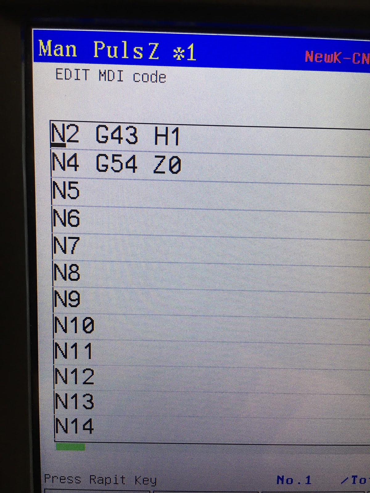
The stiffness of the quill in the head bore will hopefully ease up with use, since it must surely be the result of corrosion (humidity). I suppose I could create a short series of g-codes to cycle the head and help to bed it in.

Wednesday 24 May 2017

The elusive backlash

I now have a second DTI, so it's time to take another look at the backlash on the Z axis. This has been grieving me for the past few weeks and I am determined to work out if it there is anything I can do to improve it or if I just have to assess it and live with it.

I already had a 10um / div Baty DTI and the new DTI is a Mitutoyo 10um / div Series 1 (only £35 or so, ie not much more expensive than a China special, so why buy cotton when you can have silk?).


I'd already seen that if I set up a DTI right next to the ballnut, the backlash on the nut is of the order of 3um, including any hysteresis and noise in the servo system. That's pretty amazing for a machine of this age. The handwheel / MPG generates one pulse per um and the nut moves within typically 3 pulses after a change of direction. And the DTIs agree with the DRO.


But if I watch the movement at the bottom of the quill (that excludes the spindle bearings, to keep it simple), there is the best part of 100um of lost movement. Call it backlash or mechanical hysteresis if you like but however you look at it, that's 0.1mm of slop. And annoyingly it's between the ballnut and the quill.


So how come I have pretty much zero backlash at the ballnut, yet almost 0.1mm of backlash at the quill? That's particularly puzzling when you consider that the yoke is mounted directly on to the quill.


There seem to be only a limited number of possible explanations (root causes):


  1. The yoke is not securely mounted on the quill.
  2. There is sufficient radial wear between the quill and the cylindrical bore it runs in that the quill can move radially when the ballnut applies a load. 
  3. Surely that's it?
One downside of the ballscrew / yoke arrangement is that the quill load generates a relatively significant radial load. The yoke is cantilevered out from the quill with the ballnut on the end. So either of these causes are entirely plausible.

I previously removed the yoke, cleaned it up and refitted it, ensuring the bolts were torqued up to an appropriate setting. Annoyingly this made no obvious difference. That doesn't mean the yoke is not the problem but it would have been nice if the backlash had been fixed all the same.


So that still leaves radial movement of the quill to check for. With 2 DTIs at play, it's possible to show that the quill has NO discernible radial play going on while the 100um of backlash is happening. Furthermore, that's true no matter where you measure it on the quill. "No discernible play" means less than a few microns, compared to as much as 100 lost movement.


No need to post loads of videos and pics to document the tests (although I'll do so anyway) but it is pretty clear that the yoke MUST be moving relative to the quill, despite being firmly torqued down. The yoke shows no backlash at the ballnut end - and significant backlash at the quill end. Meanwhile, the quill only moves axially. 


One DTI set up at the ballnut, the other at the quill nose:

And again:
Here it is in action. Bugger all backlash:

If you look carefully, you can see the front of the yoke has sod all backlash, while the back is a different story:

Both DTIs checking radial movement on the quill - nothing measurable, ie of the order of microns, not hundreds of microns:

So......time to take the yoke off again. And possibly the quill too? But at least there seems to be the possibility of substantially reducing it.

Later:
Mounted a DTI directly onto the quill and looked for movement of the ballnut end of the yoke, like this: 
The amount of backlash is clearly visible with this method. So yes, the yoke isn't secure, despite being fully torqued up. Some scraping and filing required....


Cheeky chappy!!

Here's the tool setter. Looks like an interesting character!!
Merry

Monday 22 May 2017

Tool setter

I don't have any sensible means of tightening my tools, particularly the ER collet chucks. The only options currently are to grab them in the vise (with rubber jaws!) or possibly to fit them to the spindle and try to damage the bearings and spindle by graunching them with the spanner. I've gone with the first method so far but it's like trying to pin down a large fish with one hand - not very secure - and with a nasty sharp cutter sticking out, there's the chance to gain a grievous injury.

I also want to check out some of my other cutters on steel, having only cut aluminium to date. I have several carbide cutters now, courtesy of ebay etc, some of which seem to be of professional quality ie will probably get snapped by me in no time.

At this point I need a tool setter ("assembly support" in fact) but I'm not about to cough up for one.

So it's time to model up something suitable. I already have a model of the basic ISO40 tool body, having previously looked at the possibility of using BT30 tooling with the ISO40 drawbar (the conclusion is that it's not really a possibility at all), so I can build the tool setter around it.

There's basically a surface with a hole for the taper and 2 drive dogs. The taper hole would ideally(?) extend for most of the length of the taper but this would require a substantial piece of steel. I'm also a bit uncomfortable with the way these tools are generally not held in the tool positively, so I fancy having a threaded retainer to hold it while I tighten the tool. And being a tool "setter", it may be helpful to be able to mount a DTI on the front face so I can measure the tool length from the gauge surface (or a surface that is close and consistent enough for my purposes).

So rather than go for the full depth taper, I will use a piece of 1" x 2.5" stock (yes, imperial dimensions, bought in Canada) with an extension to reach and support the threaded end of the toolholder. This will be fabricated from 3 basic pieces and simply bolted together. I don't have the welders commissioned yet and threaded fasteners should be fine.

There will be a knurled bolt (not shown) in the (red) foot that will screw into the rear of the toolholder to secure it while tightening. It will be held captive with a groove in the shank of the bolt and a mating pin-ended countersink screw (not shown).

I've shown the corners rounded and chamfered, to reduce the risk of skinning my knuckles and worse. The flat surface at the front bottom will be for holding in the vise in the orientation shown.

This should allow me to try out a few operations using my carbide end mill and probably the BAP300 12mm indexable cutter with steel cutting inserts. With a 0.8mm radius tip, I should be able to get a vaguely reasonable finish in the conical bore if I specify small step-downs.

In terms of stock holding (in the machine vise), the bar stock is quite a bit longer than the model, so it will be easy to hold and I can cut off the main body after machining.

That's the plan as it stands today. I'm sure it will evolve before any metal is cut....

Tool rack

The various ISO30 (for the Blidgeport) and ISO40 (for the Shiz) tooling has developed into a bit of a disorganised pile. Apart from the mess, there's the risk of breakage and injury when these things can roll off the shelf onto the floor. While it may be nice to either cough up for some tool racks, trolleys etc or machine up my own trays, I've got better things to do. 

I also bought a piece of 18mm MDF recently that looks to be about the right size. 

Eyeing up the space on the shelf unit, I reckoned something like 400 x 500mm would fit the space and provide enough positions for the foreseeable future. Again, although I have a router and could set to up to cut out the shapes and make the holes, there are quicker and dirtier ways to get the job done, like a circular saw and a set of hole saws. The sheet was 600mm wide, so a 500mm length provides enough for the top surface and 2 verticals of 100mm  each. 

These hole saws aren't really suited to ripping holes in 18mm MDF, as they clog up within seconds. But if you keep pressing, they keep cutting. I cut through halfway from each side to get a tidy-ish finish, then sanded the faces off to clean up. Big hole for the ISO40 holders and smaller one for the ISO30s. 


Job done. Looks good enough for the likes of me:

Tuesday 16 May 2017

Tool setting saga - getting there...

This is starting to do my cake in. The guy(s) who designed / wrote the controls knew what they wanted to achieve and they knew how to set the system up when they wrote the manual (in Chinese) but without someone to show you, it's a nightmare to figure out.

It seems I have a solution finally. To my mind, the requirements for a usable arrangement are:

  • Must be able to set up a tool table, so that the program can call up the different tools - and once loaded into the spindle (they will have to be changed over manually between operations on my machine), the tool lengths should be correct (read from the table) without having to touch them off again.
  • I don't want to be having to write lengths and coordinates down from the screen and type them into another page by hand. I want this to be semi automated. 
  • The "tool setting" macros need to be understood well enough to do much of the touching off. It would be too damned annoying to know they are there but not have a clue how to use them.
  • When a new tool is loaded or a cutter is changed in a tool holder, I want to be able to set it up easily, working to the same coordinates as the existing tools.
  • Ideally I will be able to use some form of master tool - and ideally a tool setting device with electrical contacts. I suppose a simple microswitch might do. Although I have a Renishaw probe, I suspect it is too large to fit in the spindle and in my current state of ignorance and newbyness, it wouldn't last very long so would be best kept for later when I've grown up a bit.
The method that seems to work so far for populating the tool table:
  • Change to G53 (type G53 in the MDI and press the green Run button). This means we are working in absolute machine coordinates, not one of the G54-G59 work coordinate systems. This is because the tool table functions for transferring coordinate values seem to use absolute values. The box at the top of the display should show "G53".
  • Fit tool T01 and select it using "G43 T01H01" in the MDI. The "-H01" selects the tool height (length) in the first row - ideally it should be used exclusively with the first tool.
  • Run the M882 macro from the MDI. This touches the tool onto the electrical contact (or closes the microswitch, electric touch probe etc) and then stops the tool at that touch position. 
  • Press the "Redeem" button. Within the resulting Tool screen, the T1 row should be highlighted in yellow as a result of the G43 T01H01 command above. Now press "A" (redeem) to enter the current Z (absolute machine) coordinate into the (current) T1 position. Alternatively, if you are at the main screen, you can press "H" to get the same result. With the "H" option, you are prompted to select the tool number to "redeem" (god knows which translation software came up with that one).
  • NB: note again that the "A" or "H" redeem functions populate the tool length (H1 here) in the tool table with the absolute machine coordinate, which is why you need to be in G53 absolute machine coordinates. Trust me, if you are in G54 or some other work coordinate system, the redeemed value will not work for you. I spent a lot of time proving that beyond any reasonable doubt.
  • Now physically remove Tool 1 (T01) from the machine and load Tool 2 (T02) in its place, then select it in the system by issuing G43 T02H02. You don't actually need the T02 part of the command but it's helpful to do so, as T02 (row 2) will be automatically highlighted (yellow) in the tool table if it has been told Tool 2 is active. The critical part of the G43 instruction is actually the H02 (tool length 2). This tells the system that H02 tool length should be accounted for in the Z coordinate from this point.
  • Run M882 again. This will position Tool 2 at the touch point and hold it there. The current absolute machine coordinate of the Z axis is the tool length you now need to enter as H02 in the tool table in the next step.
  • As above, within the Tool screen, press "A" (redeem) to enter the current Z coordinate into the (current) T2 position. As before, the T2 row should be highlighted in yellow as a result of the G43 T02H02 command above. Alternatively, at the main screen, you can press "H" to get the same result, taking care to ensure that Tool 2 is selected for "redeeming". 
  • You should now have 2 different values in the tool table (for Tool 1 and Tool 2). The difference between the table values should be the difference in the tool lengths.
  • Check you have got sensible values by swapping the tools back and forth and issuing the appropriate G43 instructions. The critical part is the "H01", H02" etc. The "T01", "T02" etc doesn't get involved when the tool length is inserted into the work coordinate calculation. So if you insert Tool 1, you can type "G43 H01"in the MDI and hit the Run button. If all is well, you can jog the tool down to the touch level and the display should indicate zero Z coordinate there. Then fit Tool 2 and issue "G43 H02". The displayed Z coordinate should immediately change to suit the new tool length and if you lower the tool to the touch level, it should also indicate zero Z coordinate there. That's what you need to achieve. 
  • Note that when set up correctly (still talking G53 here), the machine coordinate at touch off has the same value as the tool length in the tool table but opposite sign. When the display Z coord says zero, the machine coord reads the same as the tool length (negative value). When the quill is at machine zero, the display reads the same as the tool length (positive value).
  • Now choose a convenient and different height (move the touch switch / probe to a different height) and change the coordinate system to G54 (just type G54 in the MDI and press the Run button). The main display should show "G54" in the box at the top right. Now press "Setup" and type "Z" into the dialog box - this will zero the current (G54) work coordinate system Z coordinate at the new height, as if you had touched off on a workpiece. 
  • Now check that it is working as it should. Change to Tool 2 again and issue G43 H02. This will activate the H02 tool length and the displayed G54 Z coordinate should change (by the difference between H02 and H01). If you take the tool to the touch level, the Z coordinate should read zero correctly - with this new tool. If you have managed to get it working as described, you are getting there....

Sunday 14 May 2017

Tool setting function in Newker controller

Spent a couple of hours this afternoon experimenting with the automatic tool setting functions. These seem to comprise 3 macros (M880, M882 and M883). Although they are described as "ProgramUser" macros and there is some basic description of the macro language(?), it's not obvious how you'd view or edit the contents. I downloaded the system files yesterday and none of them make any sense in a text editor, yet there are no tools provided for playing with them. The manual says you have to edit them on your PC but that doesn't help much.

There is a set of parameters relating to the tool setting function but the Chinglish describing them is particularly strong and although some of the words sound vaguely relevant to tool setting and tool lengths, it's difficult to know what the words are trying to tell you. Here's what the manual says:

2.7 Using automatic tool setting gauge

1. Notes for tool setting parameters:

Macro variables for the automatic tool setting gauge function are defined as follows (corresponding to parameters P380 - P389):
#380: The X axis machine coordinate of the initial position with automatic tool setting (mm)
#381: The Y axis machine coordinate of initial position with automatic tool setting (mm)
#382: The Z axis machine coordinate of initial position and returning point with automatic tool setting (mm)
#383: The negative speed of automatic tool setting (mm/min)
#384: The positive speed of automatic tool setting (mm/min)
#385: The Z axis coordinate of the workpiece surface in the current workpiece coordinate system after automatic tool setting (mm)
#386: The rapid move speed to the locating position with automatic tool setting (mm/min)
#387: Automatic tool setting mode (1 means fixed point, 0 means floating point).
#388: The minimum lathe coordinate value of Z axis (mm);
#389: The gap value of the Z axis [The height which is the gauge surface relative to the workpiece surface (mm)]
Fixed point gauge means putting the gauge in a fixed position, everytime the X Y Z axis are automatic running to the fixed point first in tool setting. 
Floating point gauge searches for the tool setting gauge signal along the Z axis in the negative direction.
X25 is the default input for the automatic tool setting gauge signal.

2. The instructions: 

M880 (corresponding to ProgramUser0) automatic tool setting instruction; 
M882 (corresponding to ProgramUser2) and(?) M883 (corresponding to ProgramUser3) set the gap of Z axis.
3. Automatic tool setting steps:
a) Set the No.380--No.388 parameter in “Other Parameter”;
b) Set the No.389 parameter in “Other Parameter” to define the gap of Z axis: this operation needs to be set only once.
A. Run the M882 instruction in MDI to set the gap of the Z axis;
B. Manually move the Z axis to bring the tool nose to the workpiece surface;
C. Run the M883 instruction in MDI to automatically set the gap of Z axis No.389 parameter as defined in “Other Parameter”;
c) In MDI, choose the workpiece coordinate system G54/G59;

d) For automatic tool setting, in MDI run the M880 instruction to automatically set the Z axis offset of the current workpiece coordinate system.

From my previous attempts, I know that the input X25 (aka M28) is watched by this macro and tells it when the tool setter has contacted the tool. So I connected up a banana connector (with a conveniently insulated body) to X25 and held it in the vise. Then the dummy tool (tool #1) was positioned above it. 

You can guess that parameters #380 and #381 are the position the machine needs to go to for the tool setter to be under the tool, so I copied those coordinates into the parameter screen.

Parameter #382 is simple enough - it's the spindle position that the machine needs to start from and return to before and after the tool setting macro is run. If the spindle is not already at that position, it goes there firstly.

Parameter #383 is fairly obvious once you know that it refers to the speed of the tool descending towards the tool setter when it is looking for the tool setter. If this is too fast, it may affect the accuracy of the measurement. I don't know this for certain and it depends if the measurement is actually taken on the way back in the reverse direction. I set mine to 300mm/min which seemed OK without taking forever.

Parameter #384 didn't seem to affect anything. I expected it to set the retraction speed of the tool away from the setter after touch off but changing the value didn't seem to make any difference. It's possible that another speed setting was overriding it but even setting it very low (50mm/min) didn't work.

Parameter #385 is one of those that you can guess at but in the end you have to figure it out by trial and error. In fact, it's a distance offset between the end of the tool and the G54 zero that the system sets during the tool setting process. So perhaps if your tool setter has a 2mm diameter ball or needs to be depressed 2mm before the contacts close, you would set this to 2mm. If you have a simple, solid probe and set it to 5mm, taking the tool to G54 zero leaves a 5mm gap between the tool and the zero plane.

Parameter # 386 - This the rapid speed that the table will use to go to the tool setting position, including the retraction speed of the spindle before tool setting. I found that 2000-3000mm/min is about right - much slower and it seems to take forever.

Parameter #387 determines if the tool setting mode is "fixed point"(1) or "floating point"(2). WTF?? In fact, "fixed point" means that the tool setting should be done at a defined coordinate position on the table (the machine coordinates are defined in parameters #380 and #381). If "floating point" is selected, the function is carried out at the X and Y coords where the tool is currently positioned. Only the Z axis moves.

Parameter #388 - I'm not sure what this means. I haven't tried playing with the values yet. It sounds like a sanity limit on the downward movement but I'm not convinced.

Parameter #389 - "gap of the Z axis" is the final distance between the gauge surface (the nose of the spindle) and the end of the tool.

Macro M880 - this is the main tool setting macro. Entering M880 in the MDI causes the tool to retract (to the level defined in parameter #382 at the rate defined in parameter #386), then move over to the tool setting position (X and Y coordinates defined in parameters #380 & #381, at rate defined in parameter #386), before descending towards the tool setter (at rate defined in parameter #383). When the tool setter switch closes (NC switch to 0V), the tool retracts (back to the Z position defined in parameter #382). 

The Z coordinate at the time the tool setter switch closed is now defined as the tool.......etc etc To be continued....


More backlash....

I'm getting seriously pigged off by the backlash on the Z axis. I looked at this previously and sort of concluded that the ballscrew backlash was minimal and what backlash I was seeing was due to some form of slop in the quill assembly. 

Certainly, there is the best part of 100um (0.1mm) of lost movement when I jog the Z axis up and down. It's easy to see. The ballscrew responds directly to the jogging movement from the handwheel, with negligible backlash, yet the quill itself shows lost movement. Sounds simple enough. But when I look for radial movement of the quill, I see nothing measurable. The quill end of the ballscrew yoke seems to display the lost movement, yet the ballscrew end doesn't. Can the yoke really be distorting that much?

Nasty looking wear marks on the side of the yoke bearing surface. But not obvious how this could be significant:


I removed the whole ballscrew assembly, examined it, cleaned it up, reassembled it and then torqued it back up to the recommended 30Nm (M8 hex socket cap head bolts). No change. It appears to be behaving as if it is sticking during changes of direction. If the yoke were loose, it would display this kind of behaviour perhaps - but it is far from loose. Or is it? 

Hmm. More investigation required....

Saturday 13 May 2017

Tool table progress

I think I'm sort of starting to understand what tool tables, tool lengths, tool length compensation etc are about. Spent a fruitless hour or so trying to get the controller to show that it had accepted the tool lengths and was actually doing something with them.

I thought that simply populating the tool table with some tool lengths would cause the spindle to change height when I asked it to go to G54 Z0. That's one of the many problems caused by not knowing what you are doing. 

In fact, you have to issue a G43 and accompany it with the appropriate H command. Seems the tool lengths are defined as H01, H02, H03 etc and although you should always associate (height) H01 with (tool) T01, height H02 with T02 etc, you are not forced to. And the G43 looks at the H** value, not the T** number. 

So you have to say G43 H02 for the tool length 2. Ideally, H02 is associated with tool T02. Then, when you ask for G54 Z10 with tool 2 active, it will bring the tool tip to Z10, allowing for the length of tool 2. I think.

During my recent extended stay in the armchair workshop I acquired a Mahr 3D touch probe. That's a me-too, cheaper version of the Haimer probe that is much used by Tormach owners amongst others. The drawback of this device in conjunction with a turret mill of limited Z axis movement soon becomes apparent. By the time you've mounted it in a toolholder, it sticks out far more than any tool, so the notion of setting G54 zero with it and then setting offsets for the other tools doesn't work so well. I thought I might be able to use the thing by setting G54 with an offset instead of zero but with a little bit of thought that clearly won't work. Unless I can think of some other way of making use of this device, it will have to sit at the back of the cupboard. I can't even see it being much use on the Blidgeport when that is finally converted, as it is also a turret machine with even more limited (120mm) quill movement.

You can see what I mean here. The red Mahr tool is reading zero with G54 set to zero. 
If I now swap the Mahr for a typical tool in a toolholder, the spindle has to be extended almost to the extent of its travel to reach the same G54 zero. There is almost no travel left, so unless I plan to do some engraving, I won't be able to machine anything of any height:

  Anyway, I managed to make a dummy tool (about 125mm gauge length) with another piece of 6mm aluminium rod in a 50 gauge length tool holder. This will be longer than any tool I currently own. I then numbered it #1 and with the machine coordinates at Z-1.0 (mm), I zeroed the Baty DTI and set the tool length in the tool table as tool #1. 

Next I used an ancient 1" end mill that I found in a scrapyard in Ripon when I was about 15. It's got buggered corners but it's the only tool I have that fits the toolholder that came with the Shiz - and as it's buggered, I have little to lose playing around with it. I knew it would be useful some day!! Anyway, that became tool #2. 

Tool #3 is the face mill and finally, I made the Mitsubishi indexable 12mm cutter tool #4. 

For each tool, I jogged the Z axis until the DTI read zero again ie the tip of the tool was at the same height as tool #1 had been. Then set the tool length for that tool in the table (go into "redeem", highlight that row and press "A"). The numbers look right and when I issue a G43 H* (where the * signifies the row in the tool table), the spindle moves so that the tip of the tool is at the zero defined by the DTI. 

If you add up the gauge length of each tool and the corresponding tool length from the table, you end up at the gauge length of (the master) tool 1, which is about 125mm. I suppose that's progress!

More rigid vise!

Sure enough, when I mounted my DTI to the table and measured the rigidity of the vise by pushing against it, I was able to move it about 5 thous each way simply by giving it a firm push. Not a very scientific push but enough to see that my method of raising it up on parallels wasn't the cleverest idea I've ever had.

So I repositioned them at 45 degrees or so, giving better rigidity in both axes. Still not the ideal solution but the best I can do in the circumstances. I could do with a large lump of cast iron or a box fixture, whatever they are called. The result is less than half a thou movement when I push haard against the vise. Again, hardly scientific but clearly an order or magnitude better.
 And of course I had to square it up again:

I also modified the CAD and CAM files to account for the fact that the stock is now smaller (by about 3mm in X and Y) and also to give roughing and finishing operations for both the facing and contouring, still using the same 50mm Alphamill.

This time, it's taking a 1.5mm skim off the top and 2mm off the sides, with 0.2mm left for finishing passes. The suggested default for "stock to leave" was 0.1mm but that seemed a bit thin. Having said that, the finishing cut seems heavier than I'd expected. I wonder if there is enough backlash or compliance to be causing the work to end up more oversize after roughing than planned. I will need to do some tests to investigate...

Much better finish this time not surprisingly.

The cutter is cutting about 0.66mm undersize. It's supposed to be 43mm x 92mm, so for now I have edited the tool library to correct its diameter dimension to 49.34mm. I haven't sussed out tool tables, cutter length compensation etc yet. The surface finish is better but still some way from showcase stuff. I probably need to look again at feeds and speeds but this tool should be capable of good results.

It has to be said, I've been pushing the material removal rate (MMR), which is hardly the way to get perfect finishes on an old machine. Having said that, the surface speeds are quite a bit lower than recommended.

Most of the main manufacturers provide online setup tools that will help you to determine feeds and speeds for their products. I have a snazzy carbide tool from Sandvik that cries out to be snapped by an inexperienced user like myself. The recommended feeds and speeds are much higher than my machine can handle but they give an idea of what can be achieved.

Here's Sandvik's online tool I used to find the recommended setup for their R215.36-12060-AC26L cutter.

Friday 12 May 2017

Check out

Made up a quick test piece for the face mill in Fusion 360.


I'm using the 50mm face mill to face off the top surface, then using the 50mm face mill to do a 2D contour on the vertical faces. The inserts are designed to cut on both edges, so this should work out. The tool paths look reasonable ie what I'd expect.

I don't fancy crashing my new tool and inserts on their first outing, so I'm going to do some air cutting. This will take the form of a piece of soft 6mm aluminium rod pretending to be a 50mm face mill. It's about 10mm shorter than the face mill so shouldn't make contact in the vertical axis either:
Here it is, set up at the G54 origin of the workpiece:
Had to raise the machine vise somewhat, otherwise the Z axis doesn't have enough movement to reach the bottom of the stock. If I simply lift the whole table, the guards will hit the underside of the console. So I found some 3"x1" black steel to pack it up.
Setting the vise up so the jaws are aligned with the X axis:

Here's me checking out the G54 coordinates at the front top left of the stock. I can use the MDI to move to G53 X200 Y390 where I can access the work and the vise, then move to the work origin G54, then return to the G53 X200 Y 390, as it will once the job has finished.
And doing my air cut:
The G54 origin is on the top front left of the stock. The work piece is 1.5mm that, so the depth of cut should be around 1.5mm if I set up the face mill with its control point at the G54 origin. I can set X and Y accurately enough using the 6mm rod and then set the Z axis with the actual cutter. I mean, what could possibly go wrong?

Well, nothing went drastically wrong. No broken inserts or heavy crashes. But the finish wasn't fantastic, not least on the front edges. And the final cut along the front sounded crap. Arguably I should have given it some WD40 to stop the swarf sticking to the tool but that wasn't the problem here.

Looking closely, you can see the swarf on the base of the vise dancing about. It's probably not surprising when you look at the flimsy scheme I've used to raise the vise as described above. There is also a clear step between the first and second contour passes. Seems the vise has been moving about...

I think I need to make more of an effort to turn my phone on its side when videoing.

New indexable face mill

The largest (biggest diameter) cutter I have apart from my large hogging cutters is 12mm, so if I need to face off a decent sized piece of stock before machining, it won't look pretty. Ideally I'd have a proper face mill of 50mm diameter or more so the job can be done in just a few passes. 

I've got a couple of Indian (Chronos brand) zero (or possibly negative) rake indexable milling cutters I bought some years ago before I knew anything about indexable tools. I realise now that these are pretty much exactly what you DON'T want to use in a home workshop with lightweight machine tools. They look remarkably similar to these, perhaps not surprisingly, seeing as that's where I bought them.

 I suspect they were originally designed when inserts were first being developed and their geometries were fairly crude - they have no chipbreaker and just a basic, flat-topped triangular shape. Nowadays even triangular inserts have decent top rake angles (12-15 degrees is common) and a massive range of fancy chipbreakers, materials and surface finishes. These make the cutting process much easier, resulting in a lower force / power / rigidity requirement and a better surface finish. Even with a large rigid machine, they are a much better choice.

In particular, there are inserts and tools designed specifically for milling operations including facing and side cutting. If you look at the big boys such as Korloy, Mitsubishi, Iscar etc, they are supplying a range of such cutters and inserts. In an ideal world I'd be stinking rich and would simply be able to order up what I fancied without needing to worry about the cost. It's not an ideal world though, so I have to be careful about how much I blow on tools.

My Mitsubishi BP300 indexable tool uses the AP**1135 style inserts (11mm cutting edge), so there may be advantages to using the same inserts on the face mill. However, once you get to the 50mm size diameter holders and above, the specified inserts are the larger AP**1604 inserts (16mm edge). 

For my purposes, a reckoned a 50mm or ideally 63mm tool would be good tradeoff between having a large-ish diameter tool for facing and a smallish diameter tool for outside roughing and finishing. Something like the Korloy AMCM-3050HS (see page E70) which is 50mm with 5 inserts. I agonised over the price of the thing if bought new. Even with a discount, the bottom line would come to around £200 by the time you actually provide the thing with an arbor and add in the VAT. And that's without any inserts.

Ebay finally came to the rescue. All that surfing and finger discipline paid off finally. One new, unused example came up for £100 delivered and I offered £70. Offer accepted and a genuine unused tool arrived a few days later. 

The inserts for these are between £4 (Cutwel) and £6 (APT-tools), which means another £40-60 per box of 10. However, ebay comes to the rescue again in the form of genuine(!) Mitsubishi inserts at £1 each including postage from China. They use a lot of them out in China and I guess they must be pretty cheap there. So I bought 20 each of the steel and aluminium cutting versions. Bargain buckets. They even came with a bonus set of 6 Torx screws.

And I relented and bought a face mill arbor from Cutwel for £20. They stock a wide range of ISO40 holders and their prices are about the best I've seen, even including ebay. You can also be confident that they are reasonable quality.

Here's the final assembly. I look forward to trying it out:

Final assembly and test of the spindle nose adaptor - RESULT!!

After the recent distraction caused by the 3D scanner, resurrecting the 3D printer and buggering about with the throttle bodies for my Honda...