Monday 23 October 2017

Ooops - more brown stuff and IS40 toolholders from BT40 - RIP Sir John

I  made a 30-position toolholder rack from some MDF a while back which seemed a lot at the time - but now I seem to have more than 30 toolholders. Sounds a lot but in fact that's the combined total for both the Blidgeport (ISO30 and The Shiz (ISO40).

As well as the pukka ISO40 toolholders I've acquired for The Shiz, I also got 20 or so assorted BT40 toolholders from John Stevenson not so long ago. As they won't fit the machine in their undoctored state, I planned to TIG weld some M16 threaded collars to the small end of the taper and thus make ISO40 ones out of them. Nothing to lose, as they are not usable in their current form, yet I can't imagine bothering to sell them on. And there are some useful toolholders in there. mainly ER32 collet chucks but also a couple of ER16 collet chucks and a 12mm end mill holder. 

There are a few other odds and sods such as a U Drill of unknown parentage and what look like Clarkson Autolock chucks. I also got a speeder from John that speeds up the spindle by 3:1 (max speed 10krpm), that takes an ER11 collet. Although it looks like ISO40, it actually has an imperial thread. John's machine was a Beaver which had a pullstud system, so the thread wasn't critical. To use this on my machine, I'll have to chop the end off and weld a new (M16) collar on the end. It's either that or scrap it, so again I have nothing to use.

So I chopped up the remaining piece of MDF (originally 2' x 4') and marked it out for a shit load of 44mm holes. Those bimetal hole cutters are fine - or would be if they didn't clog up every few mm of hole. That requires you to withdraw the tool and brush the teeth clear with a steel brush unless you like the smell of burning MDF.

First, an 8-position tool rack for The Shiz, to take the tools for the current job. 


Next will come a 30 position rack for ISO40 tools.....

As for the BT40 >> ISO40 transformation, here are some of the aforementioned BT40 toolholders and some collars I made up on the Bantam. There's also an ISO40 example (red collar) for them to live up to.


The collars have an internal M16 thread and are slightly less than 25mm dia. I think the formal dimension is probably 25mm or 25.4mm but it has no direct function other than to contain the drawbar thread, so it seemed sensible to make it a shade under, to allow for distortion and eccentricity in the collar and the welding operation. The length isn't critical but is typically about 25mm too. I put a heavy chamfer on each end to help with the weld on one end and for the drawbar entry on the other.


I used an M16 hex socket grub screw to align and clamp the collar and toolholder together (not the Chinesium bolt in the picture, which is as wonky as f**k), then tack welded them. Then removed the grub screw and finished the welds. No need to fully weld around the circumference. Finally, file any proud weld material down flush.

Looks good OK and functional. Furthermore they work in the machine and the runout seems pretty damned good. They are the the ones shown in the front row of the 8-position rack above. In the end, I chose a couple of ER16 collet chucks and a 12mm end mill holder as the sacrificial guinea pigs. The ER32 collet chucks and the speeder can wait until I can be arsed to machine up some more collars. I wish I had some 25mm bar stock......

Talking of John Stevenson, we heard that he died this morning, having acquired an infection following a bone marrow transplant. Bugger. He was a nice guy, generous with his time and advice and someone who simply got on with stuff rather than blather about it. His family must be grief stricken obviously.

Thursday 19 October 2017

Outbreak of The Brown Stuff - and creating multiple model / drawing instances in Fusion 360

I'm afraid there was an outbreak of The Brown Stuff in the workshop this evening but I'm pleased to say I've contained it now. At the weekend I was at B&Q getting some bags of concrete and picked up sixteen 2.4m lengths of 2"x1" treated battens with a view to finally making up some duckboards for the machines. 


I have to admit I often (usually) end up wearing my slippers in the workshop. Yes, more M&S than H&S but worst of all so far has been the swarf that gets embedded in the soles and ends up all over the house. The domestic manager hadn't twigged yet but it would be only a matter of time.

Although completely and totally unnecessary, I modelled them up in Fusion as an exercise in using the parameter table to drive the configuration and dimensions. I was also trying to sus out how to create a series of near-duplicate 2D drawings with slightly different base parts. I set it up with user parameters that specified the number of longitudinal and lateral slats, along with the width and depth dimensions. Then created a 2D drawing for each showing the centre positions, slat lengths etc. Saved me measuring and marking ten times and still cutting and drilling in the wrong places. Here's the setup for the duckboards I made for the Shiz:


Fusion is still not there when it comes to copying models and their associated drawings. To create a duplicate set, you have to archive the 2D drawing (using the A360 cloud control panel), then upload it again, back into Fusion. At that point you can rename the new files and create your alternative models / drawings. I'm sure they will get there at some point but right now it needs this work around.

The actual chopping up and screwing together was simple and quick in comparison, using a circular saw to cut bundles to the same length and a collated screwdriver (bandoliers of screws) to slap drywall screws in. I'm hopeful that these screws will be moderately rustproof.


Job done - Shiz:


Bantam:


Blidgeport:


Drawings:


Monday 16 October 2017

Tool length offset setting - how it works in practice on a knee mill

Back in June (the 18th, in fact), I learned how to use the "tool length offset" setting macro M882 to automatically set up the tool length offsets in the controller's tool table, using an electrical setting device I flashed up. It all went quite well, considering. However, since then I've been at a loss to understand how to repeat the procedure without completely resetting all of the offsets. 

The problem is that the machine uses the (absolute G53 machine coordinates) to determine the tool length offsets, yet every time I change the knee height to move the table up or down, the G53 Z height of the setting device will change and the automatically generated offsets will differ from those already stored. So unless I fancy remeasuring all of my tools each time I alter the table height, the M882 macro isn't going to be much use to me. So much for the tool setting device.

If I'm right, it suggests that the M882 macro was intended for use with bed mills, rather than turret or knee mills. With a bed mill, the tool setting gauge will always be at the same height (in machine coordinates), so this problem won't arise. 

My checking method for the last month or so has been semi manual:

  • Using my "tool length offsets spreadsheet", populated with the max/min Z heights and tool lengths for the planned job, I set the quill extension distance between the limits calculated therein.
  • Then I specify the current tool to be #13 Martest (Haimer clone) indicator, by issuing G43 T13 H13....
  • ...then change to G54 (default work coordinate system) and roughly position the WCS origin Z height to the position defined previously in CAM within a few mm, using the knee height adjustment
  • At this point, I can precisely set the Z0 coordinate by zeroing the Martest indicator scale and setting Z=0
At this point, the G54 is correctly zeroed for the planned work and the position of the quill will allow for the required range of movement.

For new tools, I've resorted to this process, which basically uses a precision gauge (aka 10.000 mm drill shank), rolled under the tip of each new tool / drill etc:
  • Gradually lower the tip using the handwheel, trying to roll the gauge under until it won't fit. Then slowly lift the tool until it just fits. Obviously you need to lower the tool, one step at a time, with the gauge clear of the tool unless you like to chip and break tools.
  • When convinced that the tool is at exactly the height of the gauge, go into the "redeem" menu, highlight the active tool (it should know this already from your G43 command), hit enter and fiddle the existing offset value so that the final G54 Z coordinate displayed is 10.000mm. There's almost certainly a simple(r) way to do it but I've been subtracting the current G54 Z value from the required 10.000 value and entering this difference value as the (incremental) tool length offset value. The offset value you need to enter is the difference between the current tool length offset and the required tool length offset.
  • If all is well, a few paranoia checks with the planned tools loaded one after the other (both physically and via G43) will end up with each tool 10mm above the Z0 height. You need to issue something like G43 TXX HXX G54 Z10 in MDI, where XX is the tool number.

Saturday 14 October 2017

Coolant hose rerouting

The original coolant arrangement was a gooseneck hose, allegedly setable to almost any position. Of course, it's a bit old now and they never quite stay where you need them. But above all, the stupid tap is mounted right at the back of the machine on the vertical face behind the spindle. This means that you have to lean right in close to the spindle to adjust the flow or walk round the side when it is running. Or stop the machine while you adjust the flow and position. 

I bought some JetOn cooling system parts from Cutwel not so long ago and initially I used a short length of flexible 15mm pipe to run the coolant to the front. I supported the pipe with a couple of plastic clips but overall the rigidity was pathetic and there was little to stop the entire hose from swivelling. 

The main JetOn coupling has a 3/4" BSPT thread. I managed to get a brass fitting with a 15mm compression joint on one end and the 3/4" BSPT female on the other. At the other end of the copper pipe, I needed a standard 1/2" BSPT male. Then a length of copper 15mm with a gentle dogleg bend. Finally, a simple bracket to support the front gubbins and stop the couplings from swivelling. Simple enough but still requiring an hour or so of buggerage.


Sorted.

Friday 13 October 2017

Swarf time - vise repair


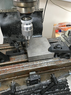
Lump held at 60 degrees, set using electronic protractor thingy. Long series 12mm HSS-Co end mill:


The surface finish is pretty shit but it's non functional and will be out of sight so now's not the time to get all anal about it. Start off the ball socket using the 12mm end mill to give it a head start:


Then use the 16mm HSS-Al ball end mill. This thing from Arc Euro is razor sharp and didn't even think of chattering. Needn't have bothered starting off with the end mill as it turns out.


The ball fits beautifully and spins easily, even without any grease at this stage.


Use the DRO to place and drill the tapping holes for the four M8 fixings. Then use a spiral flute machine tap to cut the threads under power (slow speed range). I've also drilled a through hole under the ball to allow me to push it out if necessary.


Job done:


The ball isn't ground flat yet but this shows the idea:


Now rough out the travelling jaw cavity:


Seems to fit nicely:


So now I've pretty much weakened the travelling jaw beyond any sensible limit. It must be questionable if it is still fit for purpose after this butchering. Time will tell. I'll finish the assembly etc and see if it breaks when I nip it right up.


In the longer term I need to find a decent machine vise for the Shiz so that I can move this Chinese thing over to the Blidgeport.


Drill four 8.5mm holes:


Grind a flat face on one of the balls:


Slap it in, with a bit of grease to hold and lubricate it:


Check the contact between the ball face and the flat face of the travelling nut. Looks good from here. The flat circular indent is pretty much spot on where I'd want it and the top of the nut is obviously clear of the underside of the moving jaw:


Then stick it all together:


The adjuster sticking out of the back of the moving jaw needs to be longer than in the original arrangement, on account of the different position of the mating surface (between the ball and the nut), so rather than using the original pair of grub screws, I have made up a slotted M10 screw with locknut - it does the job.

And rather than further weaken the moving jaw by heavily countersinking the 4 fixing holes, I went for the uglier solution of 4 hex head bolts. I couldn't even find any M10 washers at assembly time. The reason I couldn't find any on the shelf was because some fat bastard had left the M10 nut and bolt collection on the desk. I'll get round to fitting some later.....

Thursday 12 October 2017

Replace thrust element in Chinese vise

By the time I'd removed enough metal from the underside of the travelling jaws to find a continuous surface for the nut to act upon, there was perilously little metal left. So it seems that I will need to rough out the space and put some metal back there in the form of a steel part. 

I modelled the assembly up the other night when I was laid low with a buggered back (emptying cement bags). The required part needs to be reasonably robust - and simple so that it is not going to take me all month to make it. 


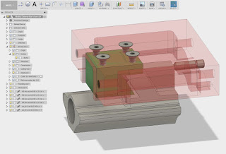
This is a drawing that shows the (grey) travelling nut and the (brown) moving jaws. The green part is the bracket I propose to make from a piece of steel. It will be held in place by four M8x25 CSK bolts. The hemispherical element will sit in a mating depression in said bracket - I'll grind a 16mm steel ball down to size.


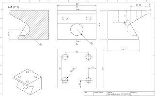
The bracket is relatively simple, although the 60 degree face will be a bit painful to machine. This is what the bracket itself will look like:


That's something to get stuck into tonight if my back doesn't complain too much.


Managed to find a piece of 2" x 2" steel. But my drawing calls for 2" x 2-1/4" x 55mm. Call me a lazy bastard - or even a fat, lazy bastard if you like - but I prefer economy of movement and effort, so how about modifying the dimensions to 2" x 2" x 57mm? And while I'm at it, I can't be arsed to attempt to machine out a 60 degree angle without a dovetail cutter And even if I did, I wouldn't look forward to the job.

So instead, I'll change the steel bracket to feature simple 90 degree angles:


Giving an assembly that has similar function but less fuss and ballache:


I think we'll find that a sight easier to flash up:


I prefer an easy life but I reckon it's also called being a good engineer. Keep it simple but achieve the required function.

Here we go. Chop chop:


I have this 3" boring head which fits the BP. But no cutters - a bit of a flaw in the plan perhaps.


But I have my BAP300 16mm indexable cutter. The shaft is a bit on the unnecessarily long side but it will do. It doesn't enhance the surface finish but won't affect the final function:


So there's the stock faced off to size. Now for the 60 degree notch.....

Tuesday 10 October 2017

Chinese vise - lipstick on a pig

The bearing arrived as expected this morning. Took a few minutes to make up a 42 x 25.5 x 7mm thrust washer, then fitted the bearing and washer to the leadscrew. Looks good.


Before reassembling the Chinese Kurt clone vise, it seemed rude not to check the rest of the functional parts. Given that the castings were so rough that the machine slide surfaces weren't even skimmed, you'd have to wonder what else they missed.

The "angle lock" feature of these vises is designed to pull down the travelling jaw to prevent it being lifted by work held near the tops of the jaws. As you can see from this Kurt D688 manual / exploded drawing, the travelling nut has a slanted face (60 degrees to vertical) and there is a sort of half ball bearing sitting in a hemispherical socket in the travelling jaw. This is to take up any misalignment of the 2 faces. Ideally they would be perfectly parallel but that's not easy to arrange.


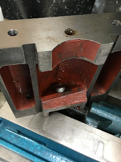
As you might expect, the travelling jaw casting is rougher than a bear's arse and the faces that should be at 60 degrees (and ideally parallel to each other) are miles off. Sure enough there is sort of vaguely spherical hole nearby that was packed with a sort of heavy grease and retained a sort of hemispherical thing. But in fact, a blind man could see that the hole was so far away from where it needed to be that it wasn't even making contact. This is what a Geordie would call "a poond of shite". If you look carefully, you can see a sort of almost-spherical thing sitting where it has a safe view of the action:


Using a bit of Blutak to show me where the contact is being made gave the game away. The "beak" of the nut barely makes it over that ridge, beyond which the spherical indent awaits.


It looks almost as if the vaguely hemispherical ball thing was thrown in for good luck and only the stiffness of the grease had prevented it from coming away. Clearly the nut and travelling jaws were making simple metal-to-metal contact. What a heap of shit.

Bollocks. We have now blundered deep into lipstick-on-the-pig territory. I'll need to be slapping it on with a trowel.

I've ordered some 16mm hardened steel balls from Simplybearings.co.uk I will then use a 16mm ball end mill to create my own socket. Given the challenges of trying to mill a spherical indent in the travelling jaws (lack of access), I'll actually make the indent in the travelling nut and simply mill the face of the mating surface in the travelling jaws flat.

Firstly, machine the face of the travelling nut so that we have a vaguely flat surface for the ball thing to work against:


Then set up the travelling jaw and try to machine the slanted face back to something approaching a flat surface, somewhere close to 60 degrees (although the angle isn't dead critical):


The casting was so crap that there wasn't a lot of metal left by the time I'd found a flat surface capable of taking the flat face of a 16mm ball. So there is a good chance I'll have to machine away the bottom of the travelling jaws and make a steel insert to connect the nut to it. Forget applying lipstick with a trowel - this will require a shovel. We'll have to see if the casting breaks when I give the handle full pastie.....

Then set up the travelling nut ready for the ball end mill. No, I'm not planning to use a 16mm drill but it allows me to angle the work just enough for it to clear the holder. It's a bit tight.

Next time - machine the spherical indent and grind one of these 16mm balls down to something approximating a hemisphere.....

Updating the Centroid Lathe PLC code with ATC turret mods

Previously, I edited the Centroid Lathe PLC code to make it work with my ATC turret . The reason for this is that the generic turret options...