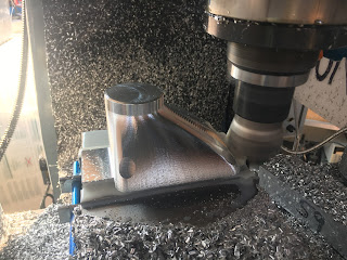
Next on the LinuxCNC system for the Bantam is the VFD interface. I need to connect up the spindle speed control (digital potentiometer), spindle enable and spindle direction outputs from the 7i76 card to the VFD. I'd also like to feed back a "spindle at speed" and/or "VFD fault" outputs from the VFD back to the controller.
I have a VFD on the machine already, set up for manual control using a multiturn pot and a couple of switches plus and e-stop. Works fine and this is pretty much what I need for the LinuxCNC system. However, it's all wired up and would require significant rework.
I have a second, identical VFD on the shelf that came off the Bridgeport when I fitted the Newker CNC controller to it. This also has a pot, on/off and direction switches etc, plus the operator panel all mounted in a diecast box. It seemed rude not to take the opportunity to fit a Yaskawa V1000 VFD, so this original VFD came spare.
If I reuse this spare VFD, I can leave the existing setup untouched, in case I need to use the lathe in manual mode the meantime. All I have to do is connect the motor to the other VFD and we are good to go. Sounds simple enough but as ever, the details will doubtless take some working out.
Wiring:
This needs a bit of rework. The remote operator, pot and switches were made up for the mill. They can come off for starters.
Here's the other VFD currently fitted to the Bantam
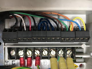
For the record, here's the new signal wiring.
I've wired it for "mode 03" ie Stop/Start (one wire), Fwd/Rev (another wire) and remote pot (speed control). There are 2 uncommitted relays that I have wired for VFD Fault and Spindle at Speed. The fault will eventually be wired into the e-stop circuit. The Spindle at Speed signal is handy to let the controller know when it's sensible to start machining.
At the 7i76 end, things are still a bit messy and will remain so until I have a cabinet to assemble these parts into. For now it's a bench lashup. Luckily most of the connections are missing from this pic.
Note that the digital outputs are all floating, as are the VFD IO. So you need to ensure the IO have a ground (0V) return to reference them to the correct level.
HAL file setup:Some changes / additions are needed to get things running. For instance, the spindle-vel-cmd-rpm-abs <= spindle.0.speed-out-abs line was missing, which is needed to feed the spindle speed command to the pid.s module, otherwise nothing comes out of the digital potentiometer. You can see why that's needed by looking further up in the HAL file:
#*******************
# SPINDLE
#*******************
setp pid.s.Pgain [SPINDLE_0]P
setp pid.s.Igain [SPINDLE_0]I
setp pid.s.Dgain [SPINDLE_0]D
setp pid.s.bias [SPINDLE_0]BIAS
setp pid.s.FF0 [SPINDLE_0]FF0
setp pid.s.FF1 [SPINDLE_0]FF1
setp pid.s.FF2 [SPINDLE_0]FF2
setp pid.s.deadband [SPINDLE_0]DEADBAND
setp pid.s.maxoutput [SPINDLE_0]MAX_OUTPUT
setp pid.s.error-previous-target true
net spindle-index-enable <=> pid.s.index-enable
net spindle-enable => pid.s.enable
net spindle-vel-cmd-rpm-abs => pid.s.command
net spindle-vel-fb-rpm-abs => pid.s.feedback
net spindle-output <= pid.s.output
# ---digital potentionmeter output signals/setup---
setp hm2_5i25.0.7i76.0.0.spinout-minlim [SPINDLE_0]OUTPUT_MIN_LIMIT
setp hm2_5i25.0.7i76.0.0.spinout-maxlim [SPINDLE_0]OUTPUT_MAX_LIMIT
setp hm2_5i25.0.7i76.0.0.spinout-scalemax [SPINDLE_0]OUTPUT_SCALE
net spindle-output => hm2_5i25.0.7i76.0.0.spinout
net spindle-enable => hm2_5i25.0.7i76.0.0.spinena
net spindle-ccw => hm2_5i25.0.7i76.0.0.spindir
The main changes are shown in bold. The inputs from the VFD to the 7i76 are on pins 04 (Spindle at Speed) and 05 (VFD Fault). The former is connected through and seems to work. The latter is set up but not connected to the e-stop circuit yet. I commented out the default sets spindle-at-speed true line, as I now have a "real" signal for that.
# ---setup spindle control signals---
net spindle-vel-cmd-rps <= spindle.0.speed-out-rps
net spindle-vel-cmd-rps-abs <= spindle.0.speed-out-rps-abs
net spindle-vel-cmd-rpm <= spindle.0.speed-out
# Added this and commented it out in the WHB hal file
# - otherwise pid.s.command doesn't have anything to work with:
net spindle-vel-cmd-rpm-abs <= spindle.0.speed-out-abs
# Added this and commented it out in the WHB hal file:
net spindle-enable <= spindle.0.on
net spindle-cw <= spindle.0.forward
net spindle-ccw <= spindle.0.reverse
net spindle-brake <= spindle.0.brake
net spindle-revs => spindle.0.revs
net spindle-at-speed => spindle.0.at-speed
net spindle-vel-fb-rps => spindle.0.speed-in
net spindle-index-enable <=> spindle.0.index-enable
# ---Setup spindle at speed signals---
# sets spindle-at-speed true
net spindle-at-speed <= hm2_5i25.0.7i76.0.0.input-05
# Not connected up to e-stop cct yet:
net vfd-fault <= hm2_5i25.0.7i76.0.0.input-04
This seems to work as intended although I had to comment out a couple of lines in the wireless pendant HAL file (xhc-whb04b-6.hal) to avoid startup errors. Not 100% if this is an issue but for now I have a result.
Took a while to figure stuff out. mainly the connection to the pid.s module and the fact that some connections are actually made in the whb04b HAL file.
That'll do for now....


