Right, so having gone through the motions with the X axis (cross slide), I should now be able to set up the Z axis (longitudinal) encoder and close the loop fairly straightforwardly you'd hope.
Encoder electrical connections:
There's no documentation anywhere for the HXX glass encoder scale I plan to use here. I bought a couple of these when I was in China, planning to use them for the lathe at some point. Well that point is now, although I used the shorter of the 2 scales for the Z axis DRO on the Bridgeport conversion.
Connecting the scale up to the DRO read head on the Bridgeport shows me that it does at least work and suggests the correct pinout for the +5V and 0V wires. Turns out it suggested incorrectly but I finally got it right. There are only 5 wires and as this has A, B and Z outputs, it's clearly "TTL" output, rather then the differential (RS422) outputs seen on the spindle encoder earlier this week.
I took the cover off the read head. Not sure that filled me with confidence but it allowed me to buzz the power lines (across the electrolytic cap) and show that the 0V was not in fact the black wire...

For posterity, here's the pinout:
Pin 2 Grey 0V 7i85.3
Pin 3 Yellow B 7i85.4
Pin 4 Black A 7i85.1
Pin 5 Blue Z 7i85.7
For completion, you also need to move the pullup shorting links to the "top" position. With TTL signals, you are connecting to the A, B & Z inputs (not Abar, Bbar & Zbar etc).
With this done, the encoder shows up in Halshow. Good start, although the scaling is all wrong still.
First, the HAL and INI file settings:
Allocate a value to the INPUT_SCALE (encoder scale parameter) in the Z axis (AXIS_1) stanza within the INI file. As I have also have a "5um" scale on the Z axis (same as the X axis), this scale factor is 200 (counts per machine unit). I will have to check whether this needs to be +ve or -ve, depending how it's ended up being connected.
INPUT_SCALE = 200
Then specify this scale factor parameter for the encoder driver module:
# ---closedloop stepper signals---
setp hm2_5i25.0.encoder.03.scale [JOINT_1]INPUT_SCALE
Then restart LinuxCNC and use Halshow to check if the axis position is being correctly reported. In my setup, the INPUT_SCALE value needs to be +200, not -200. This looks pretty convincing:

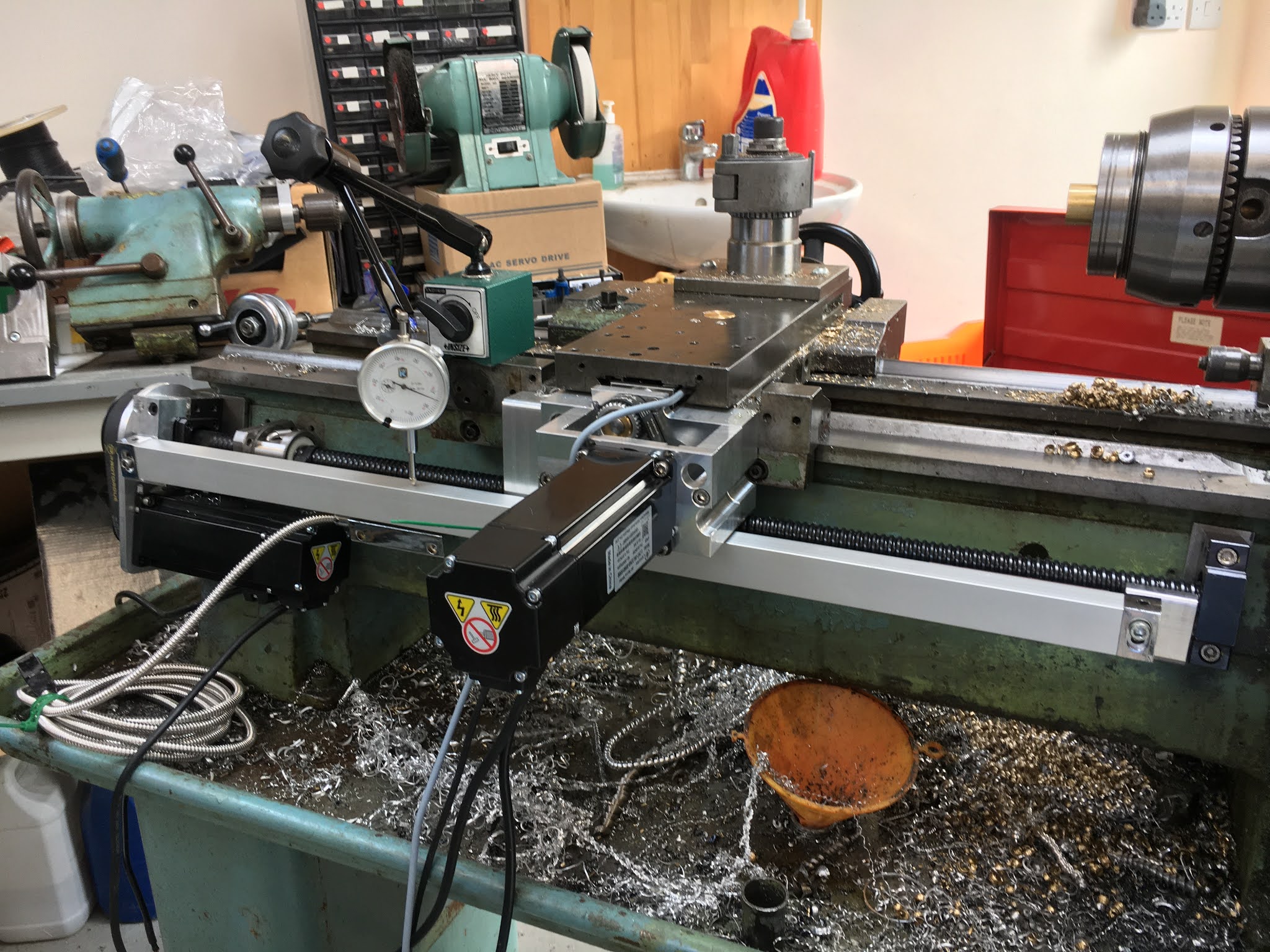
Read head mechanical setup:
The parallelism of the glass scale body to the bed needs to be pretty good, otherwise bad mechanical things could happen. This setup got it down to under a mm or so over the whole travel.


Closing the loop in LinuxCNC:
Finally, the HAL file needs to be modified to point the Z axis PID controller at the output of the encoder, rather than the position output from the stepgen driver. That requires the following change, rather like the X axis.
# Close the loop with FB from encoder:
net z-pos-fb <= hm2_5i25.0.encoder.03.position
Note that the P term in the (LinuxCNC) PID controller doesn't want to be 1000. It seems to me that a value of 1.0 would leave the control loop to the Lichuan servo - but I will come to that later, when I attempt to tune the servo drives and the outer (LinuxCNC) loop....


No comments:
Post a Comment