A couple of days ago I managed to get the controller parameters correctly set up for the revised pulley ratio used in my final(?) Z axis assembly. There's no useful information in the Chinglish user manual to guide you, so it's each man to his own. Having said that, I have a 4mm ballscrew, 1.8:1 reduction ratio and a Leadshine closed loop (integrated) stepper/drive. There aren't many ways you can do the calculations but however you did them. there was always going to be a factor of 9 in there somewhere.
The main annoyance at this point is the pathetically slow max feedrates on the X and Y axes. Clearly there is a parameter(s) limiting this. See what I mean?
Finally last night I got it sussed. There's clearly a max accel / feedrate for the Leadshine before it loses position during a speed change. But once that's been figured out, the X and Y rates need to be bottomed out, too. The pulses per rev (PPR) are different for the DMM Tech servos obviously, so the accels and max feedrate numbers will look different, too.
I'm talking about G00 (rapid) and G01 (feed rate) in particular but there are also some parameters relating to "beginning speed" and "max handwheel speed". There's more than enough ambiguity there to need experimentation. For instance, when you are running through a program using the handwheel, which feedrate applies? The guy who wrote the software (and the guy who wrote the manual) knew what he meant.
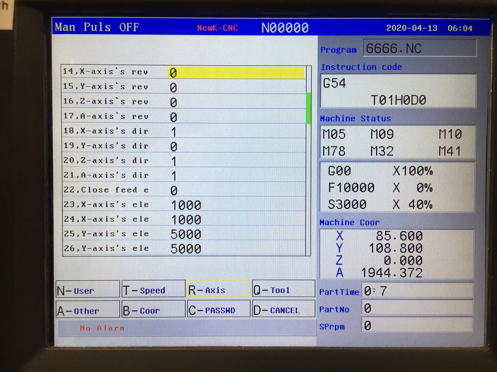
Anyway, here's what I ended up with. Much better:
Newker 990MDCa parameters:
Thought I'd take screenshots of what I have right now. Although I haven't created and run any programs yet, it looks OK so far.
Speed parameters:


Axis parameters:


Dead Proximity Switch:
I had intermittent trouble homing the Z axis, then found I couldn't move ANY of the axes in the +ve direction of travel without getting a "* Axis is in Hardware Limit" type message. I forget the exact words but you get the idea. This generally indicates a stuck +L limit switch, at which point the controller will only allow you to move away from the limit switch (ie in a -ve direction). As I don't have individual limit switches (the limit switches for all 3 axes are commoned together), this behaviour affects all of the axes.
For the Z axis, I have an Omron proximity switch. The X and Y use mechanical microswitches. They are all normally closed (NC), so the 3 switches are connected in series, with the proximity switch at the "bottom" ie switching to ground.
Clearly, the proximity switch was failing to switch to a proper low state. Sure enough, it was swinging from +24V to ~+15V. With all 3 switches in their normally closed position, I should be seeing something close to 0V. I'm guessing the threshold voltage is below 15V then, so it was (correctly) seeing a limit condition.
This is the culprit.

It wires back into the junction box on the side of the head. Makes replacement a little cleaner than having hard wired it I suppose.

What's inside?
A pair of wire cutters exposes the internals. It seems to be using a conventional ferrite pot core half as the detector element. IIRC, it switches the current in this circuit at a few kHz. It works with both ferrous and non-ferrous metals, so it's as much about detecting changes in eddy current losses as it is inductance.

Pretty basic construction inside:

That's the LED poking out:


Note the obvious mistake awaiting you. The Chinese vendor shipped me a random selection of NO and NC versions. The -MC2 is the NC version that I want here, while the -MC1 is the NO version. I was caught out by this when I first tested them out several years ago.

Wired in the replacement and it's back to intended functionality.
Yes, I know, I know, it's probably never been near an Omron factory in its miserably short life. There are all sorts of possible parentages for these Chinesium components:
- Fell off a lorry / fell out of the back door of an Omron factory
- Out of spec / test failures from a genuine Omron supplier or factory
- Unofficial extra production runs within an Omron factory
- Omron supplier bootlegging genuine products for their own profit
- Straightforward and complete cloning of Omron products by 3rd parties
- Homemade internals fitted into lookalike housings / labels
- ...anything's possible...
I'd like to say I've learnt some sort of lesson here but I haven't really. Having worked in and out of China for many years, I think I have a fair idea what to expect. I certainly wouldn't use stuff like this on a professional machine or something I'd trust my life and / or limbs with. But for a low powered hobby machine, it's a valid, low cost solution if you don't mind a bit of buggerage along the way.


No comments:
Post a Comment