Well that worked pretty well. Built up and flashed the thing and it simply worked.
Couple of minor issues:
- I need some form of power supply, as I can't sensibly expect to be powering the RPi over USB and also supply ~20V for the stepper motor. So I need to fit a 5V regulator between the 20V supply and the RPi. One of these SOT-223 regulators should do the trick, in the 5V version.
- The relay I specified turned out to be rather difficult to source. I think I bought the last stock of the one I chose. So this is the time to swap over to a more available part. Also, there's a 3V version of this Panasonic device available. Yes, a solid state part might be more exciting but I need to isolation between the Motorhead and the main welder control. And I doubt there's room for a decent sized SSR.
- Let's add a track so I can control the DIR input to the A4988 as well as the STP.
- (And as noted below, I overlooked a missing link between pins 5 and 6 of the A4988)
Schematic and PCB updates made in EasyPCB:


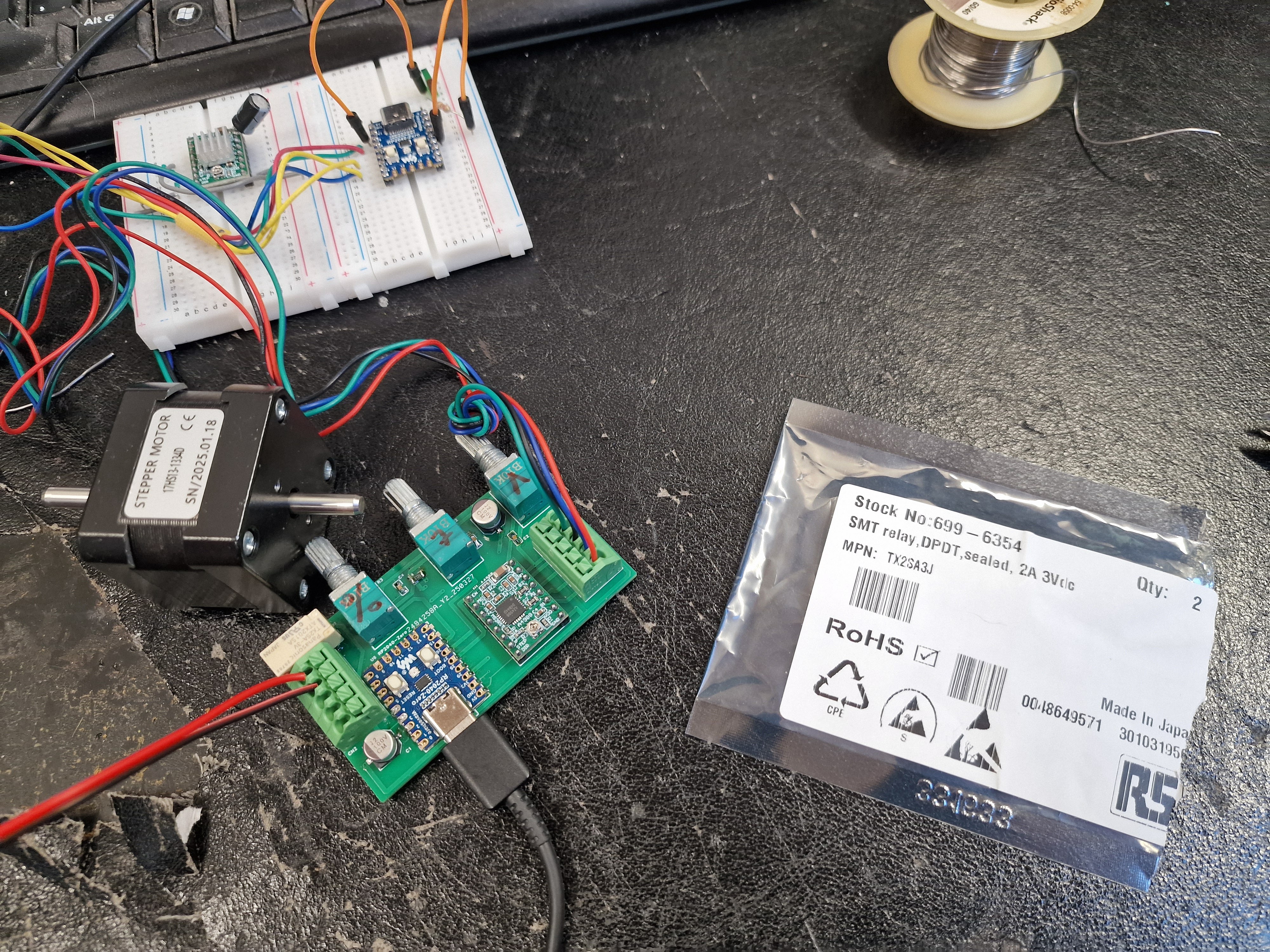
Built up first off. Would probably have taken 10-15 mins to assemble but this doubled to ~30 mins due to all the various compts being in different bags etc.


Now flash it with the final code.
The relay clicks but the stepper doesn't move or lock up. Can't easily see what I have fucked up but surely it can't be serious, as all I changed was the DIR pin. Could that be a problem - clearly not. Either way, I guess I should set that as an output and define it as either high or low.
Slightly updated code (to define DIR pin and status):
#include <AccelStepper.h>
const int pwmPin = 4; // pin 4 used for the relay pin
const int dutyCycleAnalogIn = A0; // Analog input- PWM duty
const int periodAnalogIn = A1; // Analog input - period (ms)
const int speedAnalogIn = A2; // Analog input - speed (Hz)
const int maxPeriod = 5000; // hard coded max on time
const int maxFreq = 3; // limit the max spot frequency (Hz)
const int minDuty = 0.2; // min duty cycle
const int dirPin = 2; // pin 2 used for DIR output
const int stepPin = 3; // pin 3 used for STEP output
// Variables will change
int pwmState = LOW; //initial state for PWM output
int pwmSensorValue = 0; // value read from the pot
int periodSensorValue = 0;
int speedValue = 0;
long plot = 0;
AccelStepper stepper1(AccelStepper::DRIVER, stepPin, dirPin); // (Type of driver: with 2 pins, STEP, DIR)
long previousMillisPwm = 0; //last time PWM output was updated
long previousMillisPeriod = 0;
// pwmPeriod is time between spots
long pwmPeriod = 2000; //interval between spots (milliseconds)
// must be long to prevent overflow
long pwmDuration = 2000; //interval for PWM output (milliseconds)
unsigned long currentMillis = 0; // initialise
void setup()
{
// Core 0 is used for the stepper control
// Set maximum speed value for the stepper:
stepper1.setMaxSpeed(1000);
Serial.begin(9600);
// set pwmPin to output mode
pinMode(pwmPin, OUTPUT);
pinMode(dirPin, OUTPUT);
digitalWrite(dirPin, HIGH);
digitalWrite(pwmPin, pwmState);
currentMillis = millis();
}
void setup1()
{
// Core1 setup - nothing required here
}
void loop()
{
// Relay time / PWM control is done on Core0
analogRead(0); // could be any channel
periodSensorValue = analogRead(periodAnalogIn); // 0 - 1023 count
pwmPeriod = map((maxPeriod * periodSensorValue / 1023), 0, 1023, 1000/maxFreq, 1023); // map input to pwmPeriod - time between spots
pwmSensorValue = analogRead(dutyCycleAnalogIn); // 0 - 1023 count
pwmDuration = map(pwmSensorValue, 0, 1023, pwmPeriod*minDuty, pwmPeriod); // map input to pwmDuration - min 20%
currentMillis = millis(); // capture the current time
managePwm();
managePeriod();
reportStatus();
}
void loop1()
{
// stepper speed control is done on Core1
speedValue = map(analogRead(speedAnalogIn), 0, 4095, 400, 4095); // Define setSpeed() according to input A2
stepper1.setSpeed(speedValue); // Step the motor with a constant speed previously set by setSpeed();
stepper1.runSpeed();
Serial.print("Speed ");
Serial.println(speedValue);
}
void reportStatus()
{
Serial.print("Duty time is");
Serial.print("\t");
Serial.print(pwmDuration);
Serial.print("\t");
Serial.print("Period time is");
Serial.print("\t");
Serial.print(pwmPeriod);
Serial.print("\t");
Serial.print("Output");
Serial.print("\t");
Serial.print(pwmState);
Serial.println("\t");
}
void managePwm()
{
//check if it's time to change the PWM output yet
if(currentMillis - previousMillisPwm > pwmDuration)
{
//store the time of this change
pwmState = LOW;
digitalWrite(pwmPin, pwmState);
}
}
void managePeriod()
{
//check if it's time to reset the output yet
if(currentMillis - previousMillisPeriod > pwmPeriod)
{
previousMillisPeriod = currentMillis;
previousMillisPwm = currentMillis;
pwmState = HIGH;
digitalWrite(pwmPin, pwmState);
}
}
Ah, The Stupid Fat Bloke had overlooked a missing connection between the RST (reset) and SLP (sleep) pins on the A4988. Useless idiot:

Fixed that with a blob of solder and corrected the schematic / layout. All works as intended.
Good - now back to the housing design.....