I'm not certain how to proceed with the ATC (Shiz toolchanger) for the moment, so perhaps I should focus on the CNC conversion for now. I was proceeding nicely on that project when I was offered the ATC, at which point work came to a halt. Shortly afterwards I started the new job 200 miles away. Hmm.
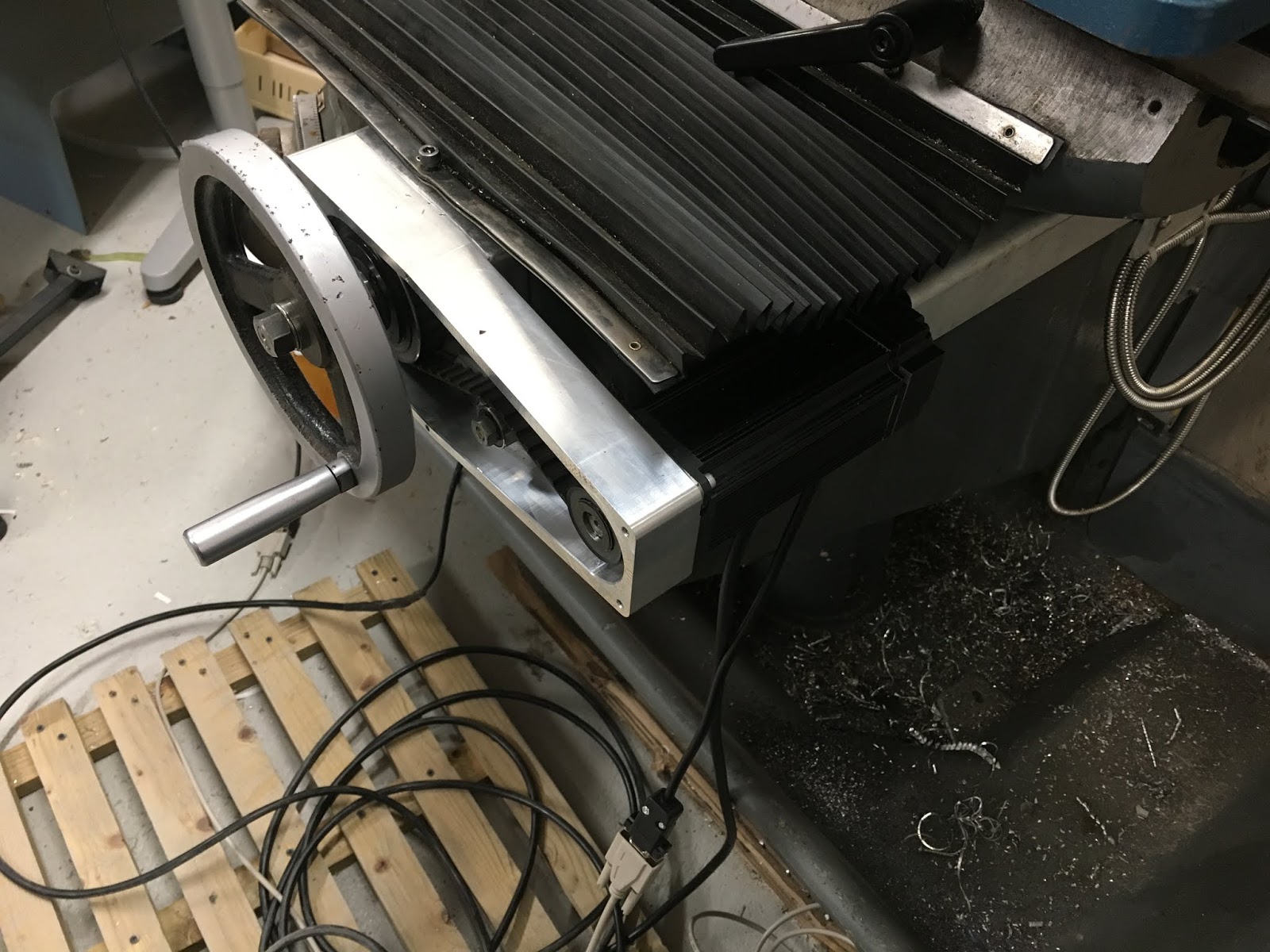
Here's where I left it last time. I'd fitted the bracket, motor, tensioner, pulleys etc for the Y axis and pulled the handwheel off the end of the X axis ballscrew, ready to fit the X axis parts.

Here's the clearance between the motor and the table / DRO scale. Seems I made a reasonable job of measuring and modelling it up way back when I designed the components.

Front view:

The coolant drain hose connection will even go back on, once I've finished fettling the rest of the parts.

Here are the main components for the X axis drive. Taper lock pulley and grub screws, key,
M12 fine nut and various washers not shown.


Quick skim of the OD for cosmetic purposes mainly:
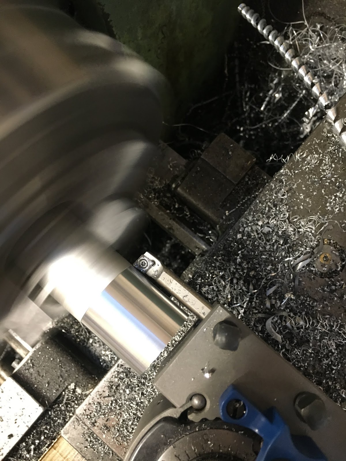
Job done:

Motor in place, tensioner fitted (moves in a slot to tension the belt):

There we are. Mustn't forget to tighten the grub screws in the Taper Lock pulley at some point. And here's the Y axis I fitted previously:
Next - do some more tuning with the DMM Technology software, then perhaps consider tackling the Z axis parts.


No comments:
Post a Comment