Right. Everything looks good to go, so let's get it on. It's not going to be just a question of bolting stuff on and powering it up....
Firstly, fit the extension piece to the ballnut protector, so I can slide it onto the ballscrew without my balls dropping, fnnaaaaar!!

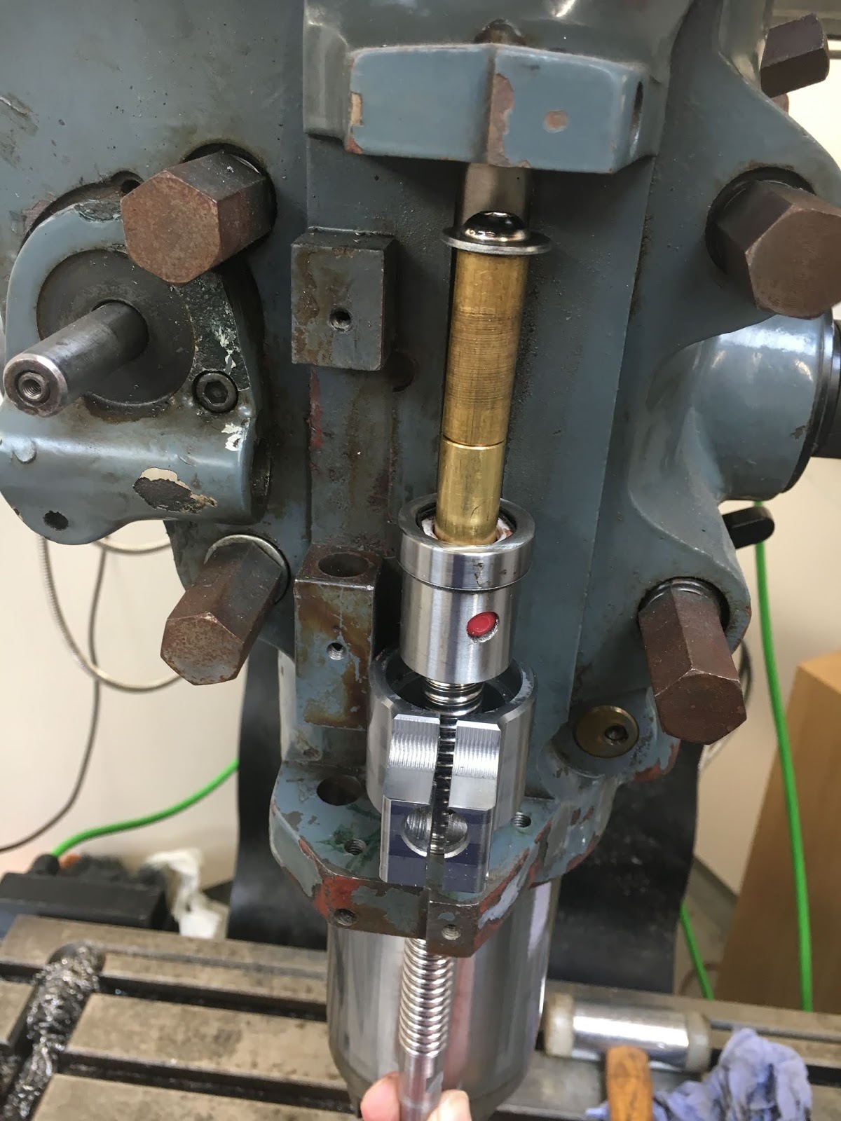
In place, ready for the ballscrew:

If I could get the ballscrew to drop down into the yoke, I'd be able to remove the tool. However, the yoke is sticking out too far. I forget how / when I measured the dimensions on this machine but it was certainly at least 4 years ago. Bottom line is that some careful measurement shows I need to remove 0.270mm from the cylindrical face on the back of the yoke, where it mates against the quill.
Fettling the yoke offset:
Take it off again and mount the yoke on the lathe faceplate. The tip of the internal grooving tool is sitting on the axis and I can use the graduated cross slide dial to move it back to the required 42.16mm, at which position it skims the existing surface of the yoke. Then move a further 0.73mm.

Checking it's coaxial with the lathe:


Off we go. The outer (tailstock end) face first, using power feed away from the headstock.

Then the faceplate end, hence the internal grooving tool to reach round the other features, using power feed towards the headstock. The tailstock is being used to help me return the tool to the correct position.

Woooh!

One benefit of liberal application of WD40 is the mirror-like reflection which helps to gauge how close the tool is to clashing. The carriage stop can't be used, as it would clash with the faceplate.

It's pissing down outside and these wood pigeons look fed up. They look ready for the pot...

Some sums:

Clearance for the yoke: A bit of bodgery to provide a bit of clearance between the yoke and mountings for the trip mechanism scale, using the angle grinder. A bit of polythene to contain the nasty grit, then try it again. We'll call this "machine fitting".

Back together again. That's better:

Pleased with the belt tensioner. I designed that using the Solidworks belt tool which has positioned the tensioner perfectly.

Preloading the thrust bearings and flashing it up:


Setting the parameters:
Yep, seems to work nicely. Obviously the scaling isn't right, as it still has the parameters from The Shiz. That had 1:1 belt ratio, 5mm pitch and CNCdrives servo drivers. This system has a Leadshine closed loop servo, 18:22 belt ratio and 4mm pitch.

Quick ballpark check on the backlash. Seems to be around 60-70um, which is probably about what we should expect with this crappy Chinesium ballscrew. I might look into this a bit more closely at some point:

The Leadshine motor is set up for 8000PPR:


The sums are fairly simple: 4mm per rev of ballscrew; 18:22 belt reduction and 8000 pulses per rev.
(4000 um / 8000 pulses) x (18 / 22) = 9 / 22 = 900 / 2200:
Axis #27 (numerator) = 2200
Axis #28 (denominator) = 900

Job's a good 'un.
There. Need to make up some proper wiring for the motor and then look at fitting the limit switches....


No comments:
Post a Comment