Here they are. 8mm bore fits the motor shaft and the max diameter is small enough for it to fit through the hole (= slot) in the housing.

So now I can see how well it all goes together. I'm planning on having some adjustment on the radial position of the ballscrew relative to the 16mm hole in the head casting but in the event, I made some of the dimensions close to the nominal and will need to do some finessing before it fits together as I intended.
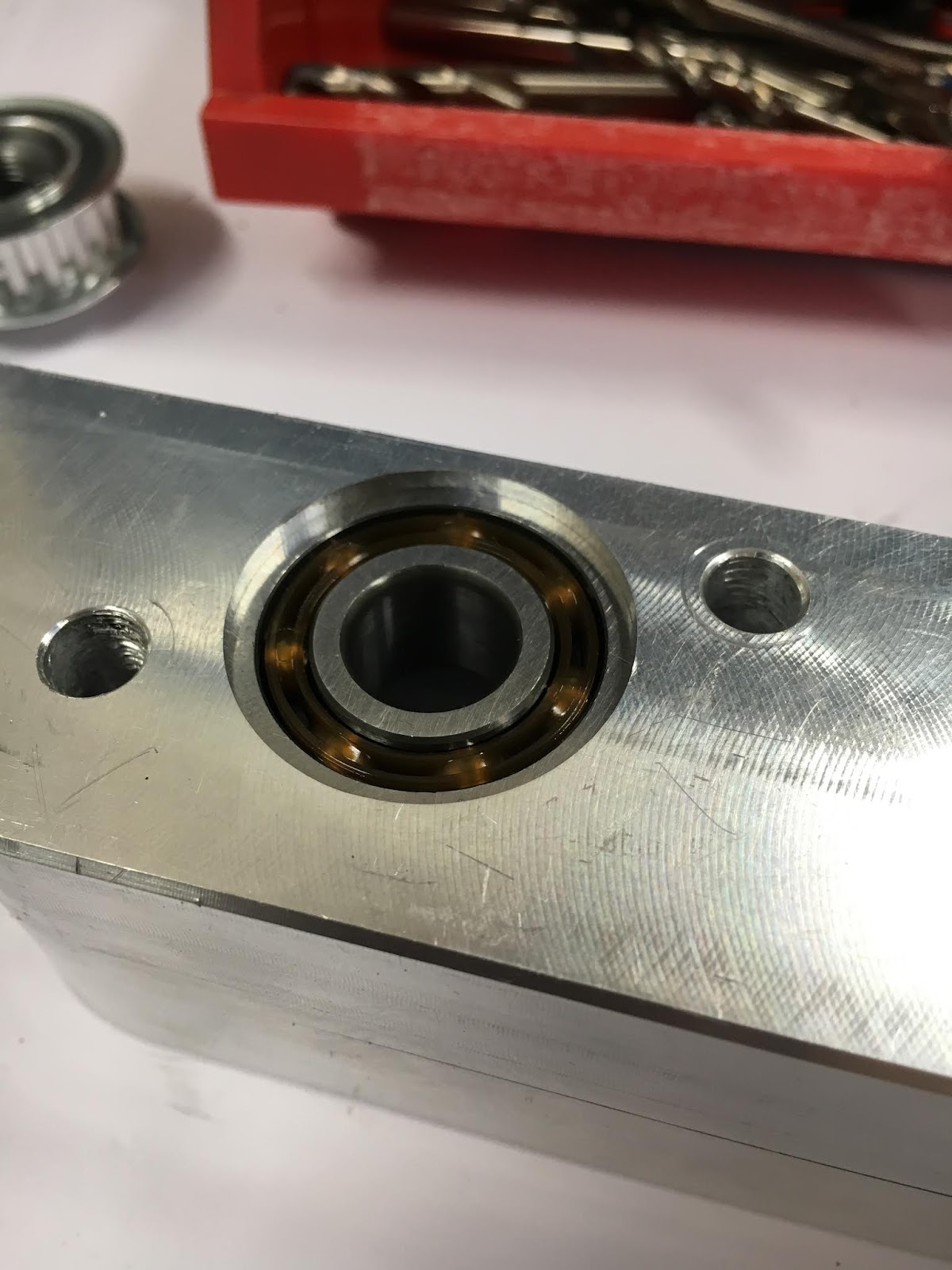
Pressed the new bearing into position - wasn't too tight a fit and I could alsmost imagine being able to press it out again if required. I'm wishing I'd gone for the sealed version of these bearings, as they are at risk of attracting dust. Obviously I left the procurement to The Stupid Fat Bloke, with predictable consequences.

I can now see (access) the bearing outer race, so it would be possible to turn up a drift if / when I need to remove the bearing later, rather than try to drive it out using the inner race which would most likely bugger the bearing entirely..
The 2 mounting holes have been opened out to 6.8mm. Given that these are for M6 caphead screws, they should never have been 6.0mm to start with. Furthermore, as I plan to allow a fair degree of slop in these fixings for final alignment of the ballscrew, they should end up closer to 7.0 or even 7.5mm diameter.
Now I can trial fit the ballscrew, sleeve and ballscrew retainer nut and see how it plays with the head casting. My design concept would allow for the motor / bracket / ballscrew / bearing / belts to be pre-assembled together, inserted into the head casting and then fastened in place with these 2 machine screws. The aforementioned slop would then allow the assembly to be aligned correctly with the ballnut so that the ballscrew doesn't end up going out of vertical as the quill moves.
Finessing required:
- Open up the holes for the M6 fixings, as described above. Possibly also the counterbores for the capheads.
- Reduce the diameter of the ballscrew down to 15mm - up to a height of 15mm above the casting. This will allow some radial slop on the ballscrew within its bore, without which it will be difficult / impossible to insert the ballscrew and its assembly into the head. Obviously I need to avoid compromising the "active" part of the ballscrew where the balls will do their thing but I know I have some margin here. I'll need to do some measurements and sums to figure out what can be achieved safely.
- Reduce the OD of the ballscrew where it sits within the casting. Until now I've done this by fitting a thin walled sleeve but it would be better simply to reduce the shaft. As well as reducing the part count, it would have the added benefit of allowing a beefier shoulder for the bearing to abut against. The sleeve is only required to support the bearing preload.
- Provide a (turned) concentric feature at the "top" of the ballscrew. This would be nonfunctional but would be useful when it comes to aligning the ballscrew. There is already an M8 threaded hole for the ballnut keeper at that end.
- Provide a bit of clearance between the housing and the head casting. Otherwise, we won't be able to take advantage of the slop. Currently it sits right against the vertical face
- Draw up a drilling jig for placing the two M6 tapped holes in the head. Getting these halfway right is somewhat helpful.
- Make the ballnut bracket narrower where it pokes through the head casting onto the quill. I have left minimal clearance in my desire to reduce any rotational movement of the quill. I measure about 16.10mm across the bracket feature and closer to 16.00mm across the slot. I'm guessing it's designed to clear a 5/8" feed stop, which would be about 15.87mm or so.
- Seems pretty clear that the ballscrew is still positioned too far from the quill. That's down to the bracket dimensioning. I'll need to check how the ballscrew / ballnut / yoke line up with the bore of the head casting to see if the yoke is OK or the problem is confined to the housing....
- Yoke (ballnut bracket) - round off the top to maximise the allowable vertical travel. A square body will stop 8mm from the top of a 16mm slot with rounded ends. In fact the quill stops with the fixing screw centre ~13mm from the top of the slot, which coincides with the top of the bracket reaching the top of the slot. I simply need to round off the bracket feature to a radius of ~8mm.


No comments:
Post a Comment