Monday, 20 April 2020

Chinesium tool setter for the Blidgeport

Chinesium special delivery:
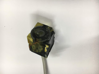
Bought one of these from AliExpress recently. It's one of those electronic tool setter thingies.


It seems to be a slightly bigger brother to the one I've been using on The Shiz for some time now. It's not pretty but it has been working fairly consistently - so far.

No need to take mine apart, as Marty has already done that for us. No need to scare ourselves really but it's interesting to see what is within:


How does it connect up?
Luckily, the only instructions are in Chinese. So using the power and might of Google Translate on my iPhone, here's what I can spy:


Seems the green and yellow are the contacts that should be used for the tool length setting and the red and black are for overtravel detection. So you'd probably wire them into your e-stop circuit. Sure enough, if you depress the detector, the green / yellow changes state from closed to open almost immediately. Press further (about 1-2mm) and the red/black then go open circuit. Not sure I can be arsed to wire in the overtravel but the detector function is already wired to the front panel since I'd previously connected up my homemade detector to a 4mm banana socket.

Not sure WTF the included connector is for. It doesn't fit the conduit (which is too big), or the threaded section of the gland (ditto) and the internal cable itself is too small. Besides, the threaded gland doesn't come with a nut and it appears to be some weird thread. I measured 20 tpi and a diameter of 0.305", which makes it neither 1/4" nor 5/16". No, it's not metric either....

Mounting the fucker:
Not in the biblical sense obviously. No - it's time to make something on the lathe. I have an M10 x 1.5 die and some handy brass bar. The cable is 4.5mm diameter, so I can drill a clearance hole through, create a counterbore for the 8mm conduit and then thread the nose M10. I can then open the 6mm hole on the front panel up to 10mm and wop the thing in there.


That should do the trick. Now for the wiring....


Sunday, 19 April 2020

Investigate crappy Y axis backlash

What's the score?
Last time I looked, it was about 390 - microns of backlash on the Y axis. That is almost unmentionably shit. WTF is going on? It should be pretty quick and easy to get an idea whhere that's coming from.

Manual test:
No need to get busy with the CNC system straight away. Simply turn the leadscrew by hand, backwards and forwards until you can see when the DRO starts to change. With a bit of practice, it's clear there's about 4mm of movement at a radius of 35mm. Simple maths shows that's equivalent to about 100um movement on a 5mm ballscrew (it's ~23um per mm of circumferential movement). That explains a fair bit. But given that I have no slop in the belt, that's less than a third of the measured value. Something doesn't add up. Literally.

Wait a minute...
When I turn the handwheel to move the saddle in the negative direction, the DRO actually shows an increasing reading initially, followed eventually by a decreasing reading. The DRO scale is mounted on the side of the saddle, whereas the ballscrew drives the saddle at its middle. It appears that the saddle does some sort of twist about a vertical axis but that isn't sensibly possible.

Here we go. One of the fixing screws had fallen off the Y axis DRO scale bracket and allowed the read head to wobble about as it moved. This caused it to drag against the cover and behave as discovered ("moving backwards initially, before finally moving forwards"). I took the brackets off anyway to check I wasn't missing anything and reassembled them, replacing the missing screw. 


Job done. 


Seemed a good idea to remove the black streaks caused by the abrasive contact while I was at it. That's better:


And?
Now the bad (but slightly better) news. The Y axis backlash is now a consistent 100um. That compares to the X axis which manages about 35um. I guess that's down to the ball bearings, which I don't plan on messing with at this stage. It's still shit - but I guess that's what you get when you buy Chinesium ballscrews from AliExpress for peanuts.

Wednesday, 15 April 2020

Unloaded backlash measurements on the Blidgeport

Why spoil a good thing?
So far this has been very gentlemanly. The CNC conversion of the Bridgeport clone appears to have gone together nicely and be working as you might hope. But is it? At this stage, most of the Pootube Warriors would be bragging about "holding tenths" and other bollocks. This is a fairly old machine fitted with Chinesium ballscrews, so accuracy and backlash aren't going to be anything to write home about. However, there's nothing like measuring what you've got in your hands and asking yourself if it's what you'd expect - and be happy with. If not, it's time to either swallow your pride / adjust expectations - or go back and have another go.

How to do it?
Using MDI commands:

          X0      ;  Start at zero
          X10    ; Move to +10mm
          X0      ; Return to zero from above. (Set DRO to zero here).
          X-10   ; Move to -10mm
          X0      ; Return to zero from below. (Read DRO measurement here).

Like this:


Then edit / repeat for Y and Z axes etc.

When I say "Set / Read DRO", I'm referring to the independent (HXX) Chinesium DRO which has its own glass scales on the X and Y axes, not the display on the Newker controller. I won't be able to use the DRO for the Z axis until I refit the scale there so for the time being I will have to use a DTI for that instead.

This example should give an idea of the unloaded backlash in the X axis. Of course, a loaded machine will see bigger backlash but for starters, this should give an idea of what we are dealing with here. I can then look at how much more horrific it is when an actual load is applied (gulp!).

To run this on the Newker controller, select "Single" mode from the front panel keyboard. This allows you to step through the MDI commands one line at a time each time you press the green "Start" button. The title bar on the display should say "MAN INC 1.000" which sort of makes some sense - when you know what it's doing.

Results:
X axis - total 30um. Gave a very consistent reading over 5 runs. And the positional accuracy in the same direction is bang on over the first 100mm or so. TBH, 30um seems about what I might expect. It will be interesting to see what it increases to when I present it with some sort of preload to simulate a cutting force that is trying to return the tool to the zero position. That won't be so pretty....

Y axis - total 390um. Oooof. Yes - clearly something amiss there. Time to check out the assembly. I doubt that can be down to the ballscrew alone. More likely to be due to the ballnut being securely fastened in place or (preferably) due to the bearing / pulley / ballscrew not being correctly tightened up.

Z axis - total 100um. Actually 0.004" using an imperial DTI. Oooof again. That's even shitter than I'd expected. This requres further investigation. I could live with ~1/4 of that ie closer to that of the X axis.

(note the HXX DRO only reads 5um increments).

Oooof. 
Wasn't expecting nano scale accuracy but even if I get the Y axis sorted, the Z axis is still nothing short of abysmal. The most likely culprit is going to be the ballscrew and ballnut but a methodical investigation is going to be required before I start looking at messy corrective actions such as fitting larger ball bearings etc.

At this stage, I could hear The Stupid Fat Bloke muttering something about not having finished setting up the machine yet. I'm not sure that's the way to look at this but it's true to say that I haven't really done much more than functional testing so far, whereas testing it against "reasonable expectations" is something you'd do before signing something like this off.

Next steps:
Bring the DTI to bear on the Y and Z axes with a view to figuring out the breakdown of the total backlash measurements. They won't be totally down to one component although I'm expecting to find something dominating in each case eg assembly cockup (Y) and ballscrew (Z). Time will tell - but hopefully not much of it.

Monday, 13 April 2020

Trouble at't mill - dead proximity switch and Newker 990MDCa parameters

Slow rapids - sorted:
A couple of days ago I managed to get the controller parameters correctly set up for the revised pulley ratio used in my final(?) Z axis assembly. There's no useful information in the Chinglish user manual to guide you, so it's each man to his own. Having said that, I have a 4mm ballscrew, 1.8:1 reduction ratio and a Leadshine closed loop (integrated) stepper/drive. There aren't many ways you can do the calculations but however you did them. there was always going to be a factor of 9 in there somewhere.

The main annoyance at this point is the pathetically slow max feedrates on the X and Y axes. Clearly there is a parameter(s) limiting this. See what I mean?


Finally last night I got it sussed. There's clearly a max accel / feedrate for the Leadshine before it loses position during a speed change. But once that's been figured out, the X and Y rates need to be bottomed out, too. The pulses per rev (PPR) are different for the DMM Tech servos obviously, so the accels and max feedrate numbers will look different, too. 

I'm talking about G00 (rapid) and G01 (feed rate) in particular but there are also some parameters relating to "beginning speed" and "max handwheel speed". There's more than enough ambiguity there to need experimentation. For instance, when you are running through a program using the handwheel, which feedrate applies? The guy who wrote the software (and the guy who wrote the manual) knew what he meant.

Anyway, here's what I ended up with. Much better:


Newker 990MDCa parameters:
Thought I'd take screenshots of what I have right now. Although I haven't created and run any programs yet, it looks OK so far.

Speed parameters:


Axis parameters:


Dead Proximity Switch:
I had intermittent trouble homing the Z axis, then found I couldn't move ANY of the axes in the +ve direction of travel without getting a "* Axis is in Hardware Limit" type message. I forget the exact words but you get the idea. This generally indicates a stuck +L limit switch, at which point the controller will only allow you to move away from the limit switch (ie in a -ve direction). As I don't have individual limit switches (the limit switches for all 3 axes are commoned together), this behaviour affects all of the axes. 

For the Z axis, I have an Omron proximity switch. The X and Y use mechanical microswitches. They are all normally closed (NC), so the 3 switches are connected in series, with the proximity switch at the "bottom" ie switching to ground. 

Clearly, the proximity switch was failing to switch to a proper low state. Sure enough, it was swinging from +24V to ~+15V. With all 3 switches in their normally closed position, I should be seeing something close to 0V. I'm guessing the threshold voltage is below 15V then, so it was (correctly) seeing a limit condition.

This is the culprit.

It wires back into the junction box on the side of the head. Makes replacement a little cleaner than having hard wired it I suppose.


What's inside?
A pair of wire cutters exposes the internals. It seems to be using a conventional ferrite pot core half as the detector element. IIRC, it switches the current in this circuit at a few kHz. It works with both ferrous and non-ferrous metals, so it's as much about detecting changes in eddy current losses as it is inductance.


Pretty basic construction inside:


That's the LED poking out:


Note the obvious mistake awaiting you. The Chinese vendor shipped me a random selection of NO and NC versions. The -MC2 is the NC version that I want here, while the -MC1 is the NO version. I was caught out by this when I first tested them out several years ago.


Wired in the replacement and it's back to intended functionality.

Yes, I know, I know, it's probably never been near an Omron factory in its miserably short life. There are all sorts of possible parentages for these Chinesium components: 

  • Fell off a lorry / fell out of the back door of an Omron factory
  • Out of spec / test failures from a genuine Omron supplier or factory
  • Unofficial extra production runs within an Omron factory
  • Omron supplier bootlegging genuine products for their own profit
  • Straightforward and complete cloning of Omron products by 3rd parties
  • Homemade internals fitted into lookalike housings / labels
  • ...anything's possible...
But either way, you often get what you pay for (but not always). I got something like 10 of these for around $20, so you'd have to expect a high probability of ending up with something hooky. Buyer beware, bought as seen etc.

I'd like to say I've learnt some sort of lesson here but I haven't really. Having worked in and out of China for many years, I think I have a fair idea what to expect. I certainly wouldn't use stuff like this on a professional machine or something I'd trust my life and / or limbs with. But for a low powered hobby machine, it's a valid, low cost solution if you don't mind a bit of buggerage along the way.

Sunday, 5 April 2020

Blidgeport Z axis finally assembled!

Bridgeport Z Axis - Final Assembly!
Hell's bells. I can't think of anything more I can fanny about with instead of finally putting all these parts together that I've been working on (and off) for the last god nose how long.

The bearing retainer plate fits nicely, the bearing fits its bore, the ballscrew machining is completed, the "MkII" housing / motor mount / belt housing / ballnut mount is finished and I have all the little bits and bobs required to slap it all together. What are you waiting for, fatty? 

Here's what I've got, finally. Look at how the motor fixings are bang in the middle of the adjustment slots. It could almost have been deliberate - not bad for something entirely designed in CAD.


This Chinesium 10t pulley needed a bit of its length removing. I could have drilled and tapped alternative holes for the grubs but instead I turned it as far back as I could before the grubs complained. You couldn't go much further than this. Job's a good 'un. 


The whole motor / housing / ballscrew assembly simply slides up through the hole formerly used by the feed trip rod and is held in place by two M6 screws (the only modifications required to the machine). That's the simplicity of this concept - and also why it's relatively rugged compared to the "normal" approach, where the ballnut is cantilevered out the front. 


But before getting too carried away, the ballnut yoke needs to be bolted to the quill. Obviously this will be a little more challenging once the ballnut is in place, as the access hole will be blocked.


You also need some way to swap the ballnut keeper for the actual ballscrew. For this, I've drilled and tapped the end of the ballscrew with an M8 male thread. Then I can screw on a short length of 14mm brass rod and simply slide the ballnut across.


Until then, I've been keeping my balls where they need to be using a sort of butt plug, also made from 14mm rod with M8 screws and washers:


Here we go...


I used the wrong transfer piece here (should have had a male thread on it) but it went OK anyway.


The white plastic wiper tried to make a break for it. so I had to release it and refit it later. It screws down the ballscrew, then is prevented from coming out by means of a couple of tiny, pointed grubscrews.


Finally, all is well.


Next, get the ballnut fastened to the yoke. Once this has been connected up, you need to turn the ballscrew so that the ballnut is positioned right at the bottom, next to the mounting face. Then you can tighten up the two M6 screws, knowing that the bearing is correctly aligned. I've designed the bores for the fixings to have enough movement to accommodate a sensible amount of adjustment (about +/-0.5mm). 


I may well refit the DRO scale once it's all up and running. This is what it will look like.


But for now, I'll focus on getting the limit switches set up. Drill and tap a couple of M4 holes, so I can fit a metallic target for the proximity switches to see:


Does it work, fatty?
It's been so long since I messed with the Newker controller that I've forgotten how to home the machine. For reference, the homing is done by pressing the "Return" button (bottom right panel) and telling it which axis / axes to home. It then moves up, looking for the home switch signal before backing off and setting the G53 coordinate to zero. If it doesn't find that, it will see the hard (limit) switch and stop - unless you have the speeds and accels set to stooopid values of course.

Here it is finally:

Well??
Must say, it's a lot smoother now that the ballscrew is better aligned. You might naively think that a bit of misalignment wouldn't matter so much if you have a ball thrust bearing and ballscrew setup - but you'd be wrong. I'd also forgotten how quiet the whole machine is. Not complaining, mind.

Next Steps:
Now to figure out how to set the axis scaling and speeds / accels for the Z axis. It was set up before but The Stupid Fat Bloke decided it was a good idea to change the pulley ratio to reduce the size of the assembly and increase the reduction ratio (now 1.8:1, was about 1.2:1). If you change the ratio, the axis scaling will change and your soft limits will be in the wrong place. The accels and speeds will also be all to cock, so it's best to sit down and calculate the new values. You also need to ensure the stepper driver itself has the correct steps per rev selected. In my case, I should expect that the Stupid Fat Bloke has been fiddling with the DIP switch settings on the side of the Leadshine Easyservo stepper motor. 

TIG welder up and running - after some fault diagnostics and repair

Finally got some time to connect up the flow meter and argon hose. Plugged in the torch and ground cables and the torch hose etc. Powered it...