Sunday, 29 November 2020

Swarf time - Z axis bracket

Enough of the virtual stuff. Time to cut some metal.

Apart from the trusty old 50mm face mill, these are the tools required to make the bracket.


I have some 1.5" x 4.5" loominum left over from the Bridgeport conversion. I only need ~83mm x 139mm, so the bandsaw comes to the rescue. Start by chopping off the holes in the existing stock.


And chop it down roughly to size.


Bang - the blade broke. I have a couple of brand new Starrett blades, so time for a quick clean, then on with the new one.


Manually machine up the stock to exact length (139mm). Those 10mm end mills are razor sharp still, generating bum fluff swarf.


There we go - the stock size matches what is in the Fusion CAM file.


Right - let's go. This is the first set up, drilling the through holes and machining a channel in the exposed end. That witness mark will be gone after the first facing pass...


One of The Annoying Changes that Autodesk have made to the free version is preventing tool changes between operations within the same file. No problem - I usually generate a separate file for each tool anyway and the Fusion file is open on the same PC as it is, so I can quickly generate the g-code, save it directly to the Acorn directory and load it from there.

As for the removal of rapids, it's not a big deal when you only have a few operations on a (physically) small part, so no big irritation there.

Let's go!

No pics but here's the first operation done - drill and bore holes and channel.

Flip over and pick up the datum origin from the centre of the bored hole.


What could possibly go wrong etc...


Nothing so far!


That's the main milling work completed 


The chamfer mill has to sneak down to the features within the cavity. IIRC, the clearance is a nominal 0.25mm.


That's the "inner" side operations complete. That left the "outer" features to be completed, namely facing off the remaining stock, counterboring the fixing holes and chamfering the edges.

Z bracket - done:


A couple of annoyances:

As you can see, the simulated final component has a couple of ridges either side of the cavity - that's visible in the pics if you look closely. The Stupid Fat Bloke was put in charge of generating the toolpaths here and years of self abuse and generally sloppy attention to detail allowed this to remain overlooked right to the end. Furthermore, even a half arsed inspection of the component before removing it from the vise would have allowed a followup operation to remove it. It wouldn't be a massive challenge to go back and do it even now but I refuse to be that anal. It's a non-functional, cosmetic flaw that can remain as a reminder of what a shit job I can put out if needs be.


Also, there seems to be a slight error in the longitudinal origin (whether it was X or Y depends on which setup we are talking). Although all the features within that setup were coordinated, they ended up misaligned to the previous ops by perhaps as much as 0.5mm. The result was the vertical edges at each end were either overchamfered or almost not at all. Only affected 2 edges but it's still f annoying.

And another thing. I managed to miss a couple of chamfers / fillets in the rush. Again, not a big issue so much as an annoyance. I must try to sharpen up my act. Or perhaps it's The First Sign.

But does it fit?

Well yes, at least that bit worked out OK. I haven't checked the alignment of the ballscrew with the bearing but unless I really screwed up the dimensions, there should be enough slop in the fixings to accommodate some tolerance on those - which is why I took that approach. Lessons were learned from the Bridgeport Z axis!


And yes, the bearing is a decent fit in its bore.

Next?

It may be time to start butchering the cross slide body next...

Thursday, 26 November 2020

Bantam butchery - the plan

 Is there a plan?

Well yes, it's been evolving. Getting to the point where I think it's workable ie almost time to start cutting metal. Besides, most of the parts have arrived now.

Here's the current rear view:


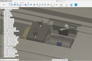
Close up of the saddle (Z axis) assembly:


Which will require the following butchery of the saddle body:
  • Widen / deepen the slot to accommodate the larger ballnut.
  • Machine 2 slots for the home and limit switches (on left of this view).
  • Machine a slot for the encoder read head (bottom right of view).
  • Er...that's it.


Here's how I plan to install the Z axis ballscrew:
  • 6200 ball bearing at the rear of the ballscrew, taking the axial loads.
  • Flex coupling at the front of the ballscrew. This simply allows manual operation of the ballscrew, as there is no thrust involved, so any minor rotational backlash isn't an issue. I have some 25OD x 30L x 10mm bore couplings on their way from Chinesiumsville even as we speak.
  • The grey bracket fixes to the saddle body using existing threaded holes (which seem to be 1/4" BSW), presumably provided for attaching the taper turning attachment.


Cross section shows how it all goes together:


The limit switches are triggered by a small, dual ramped target body fixed to the underside of the cross slide body. The tiny Omron microswitches have about +/- 2.5mm adjustment. I will need to provide somewhere for the wiring to escape.


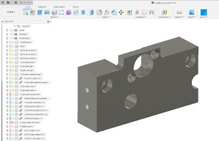
The bracket that houses the thrust bearing (that mounts to the rear of the saddle) is fairly simple: 
  • The mounting holes are for the aforementioned 1/4" BSW screws and I've provided them with about 1mm of slop so I can adjust the position to ensure minimal misalignment of the ballnut. 
  • The 2 large through bores are for the rear saddle gib strip which needs to be accessible so I can adjust them in position.


I can just about see my way to machining this from the piece of 4" x 1.5" loominum I have left over from my Bridgeport X and Y axis housings.

What else, fatty?


Yes, that's the delivery from Lichuan ie the servo drives and motors. 


That looks pretty painful. Setting up a servo drive can be a royal PITA yet there is no software to assist, so it will all have to be done using the front panel buttons. This could be character forming...

I've also got all the pulleys, belts (both axes), bearings (cross slide) and taps (M2, M2.5, M10x1.0 etc required for mounting the microswitches, encoder head, making the X axis ballscrew nut etc).

The more powerful motherboard is on its way (should be here tomorrow perhaps), the PCI-e to PCI adaptor arrived yesterday (needed so I can re-use the 5i25 - very few mobos these days still have a PCI slot), as did the second D25 connector for the 5i25 and its D25-D25 cable (each of the 7i76 and 7i85 require their own cable back to the 5i25), the 7i85 card arrived on Monday and I received a selection of M2 and M2.5 button head and cap head screws from Kayfast Ltd.

I even received my book on Linux Mint 20. My last one was for the 2013 Ubuntu edition which is thankfully obsolete. Mint has moved the game on a fair way since then, thank Fook.

Finally, I need to figure out how to control the servos using Modbus RS485. I've belatedly ordered a USB-to-RS485 adaptor so this is something else I need to get into. I hope to control them from LinuxCNC over RS485 - apart from the step / dir signals presumably.

No excuse for sitting about then!

Saturday, 14 November 2020

Bantam CNC - sequence of events

 There's a right way to do this:

Some of the critical machining work will need to be done on the lathe itself - stuff like modifying the existing X axis (cross slide) leadscrew and perhaps machining up the housings for the ballnut and thrust bearing for the cross slide. It's a question of "physician heal thyself", something that can't be done while said physician is out of action.

What to do first? Seems to me I should get the cross slide assembly done first, then move on to the saddle. Rather like doing the Z axis on the Bridgeport conversion before the more straightforward X and Y drives, as that's where the tricky stuff lay.

Sequence of events:

  1. Clean up the cross slide and saddle bodies and machine the cavities for the encoder scale, limit switches etc. Ideally but not necessarily including the ballnut yoke fixing holes, if I can finalise them in time. This will be done on the mill.
  2. Reassemble the lathe (apron, cross slide, power feed shaft etc), so I have a functioning machine again. Obviously I will need to mount the modified motor and recommission the VFD at this point.
  3. Machine up the cross slide thrust/drive housing and the cross slide ballnut yoke. These will likely require boring in the lathe but otherwise is mostly milling.
  4. Bore out the Rotex coupling for the cross slide ballscrew drive and the driven pulley, then machine up the cross slide ballscrew. This needs to be done on the lathe.
  5. At this point, the old leadscrew can be chopped down and the new ballscrew, ballnut, yoke, thrust bearing and pulley fitted.
  6. The drive servo could be fitted at this stage, although it would mainly serve to show it assembles correctly.

If this goes well, I should have a functional manual lathe with a ballscrew cross slide (X axis) and a servo drive. I can then move to the more straightforward saddle drive (Z axis), glass encoder scale etc.

So first, before I can proceed much further, I need to make my mind up about the saddle and cross slide mods I will finally go for. Although I'm not shy when it comes to machining the original parts, I'd rather not end up making a pig's ear of it.

The cross slide itself is fairly simple - machine a shallow slot on the hidden underside of the body to receive the magnetic trip. Then drill and counterbore the fixing holes for the ballnut yoke. I may do that later, as removing the cross slide is fairly easy.

The saddle is a bit more involved. Requires cleaning up the rough cast leadscrew cavity and making some slots for the encoder body and the limit switches. Let's get those features finalised next....

Tuesday, 10 November 2020

Latest progress on the Bantam CNC conversion - CAD assembly

So how's the CAD work going then, Fatty?

I've put lots of effort put into this recently. At least I seem to be making some sort of progress. I'm not the kind of guy who just holds a part up against the machine, screws it in place and then figures out how to add the next bit. There are a lot of moving parts here and not a lot of space.

I've modelled up most of the critical parts to a appropriate degree of accuracy, so I can design stuff to fit together with a fair degree of confidence that it will assemble and work.

Here's the section view through the cross slide ballscrew. I've got a simple rigid sleeve shown here but that wouldn't allow any float, which would make setup and adjustment rather tricky. In fact I plan to have a 14mm Rotex "spider" coupling joining the new ballscrew and the original leadscrew stub. 


The back of the machine is looking somewhere between "busy" and "tricky". I hadn't realised the mounts for the large ballscrew would be so large. Fitting them and the saddle and the ballscrew and the encoder scale in that space will take some juggling to end up with a tidy solution. Looks workable but isn't your slam dunk.


From another angle:


And stepping back a bit:

The "missing component" that houses the cross slide ballscrew thrust bearing, connects the saddle to the saddle ballnut and picks up the encoder read head will be a critical part. It also holds the servo motor, houses the drive belt and pulley and provides some adjustment to adjust the belt tension and align the saddle ballnut.

Next - figure out a sensible solution for the "missing part" that I can make without needing a PhD in machining....

Saddle ballscrew assembly - getting some bits together

Preparing to get on with the Bantam CNC conversion

Here's what I've got in the pipeline, heading its way from various emporia in Korea and the UK. Spending beer tokens is the easy bit, although getting them in the door past the Domestic Manager can be fraught. But that's no reason to hold back.

Ballscrews:

I've gone for parts from the DY Global scrapyard in Seoul, stripped from some bygone machine or other. Rather than take my chances with some shark on AliExpress flogging bent (literally) rolled ballscrews, I thought I'd go for second hand decent ground jobbies. In some cases, they offer new old stock parts from the likes of HSK, Hiwin, TBI etc. In this instance, there was nothing suitable for my needs. However, I finally settled on the following:

1205 ground ballscrew for the cross slide. I've convinced myself the ballnut will (just) fit in the cavity in the saddle under the cross slide. I'll clean up the rough cast cavity to give it a bit of margin but it The ballscrew itself is longer than I need but I'll machine it down when I have actually designed something for it to go in.


And a 2005 ground ballscrew for the saddle. It's longer than I need but as I'm not yet certain what that is, I'd rather cut down a longer ballscrew than curse a shorter one.


From DY Global's description:

Main Size (Metric) 
  • Shaft Diameter = 20mm
  • Lead  (Pitch - distance by 1 rotation) = 5mm
  • Nut Diameter = 44mm
  • Flange Size = 60mm X 44mm
  • Nut PCD = 55mm
  • NUT Length = 41mm
  • Overall Length : 1090mm
  • Helix parts Length : 980mm
  • Motor Side  (Fixture Part) diameter for coupling : 12mm
  • Motor Side  (Fixture Part) diameter : 15mm (applicable to AK15, EK15, BK15, FK15)
  • Support Side diameter :  15mm (applicable to AF15, EF15, BF15, FF15)
  • Ball Screw Support Unit : BK15+BF15
Ballscrew supports:

The big one seems to come with a set of supports. These are the generic BK15 and BF15 supports that you see on all the Chinesium sites. There's a reasonable drawing here ballscrew supports - Hiwin.

And for the ballscrew / ballnut themselves, the Issoku ballscrews home page is a good start. Issoku HTR2005C7 ballscrew (page 68) and Issoku HTR2005C7 ballnut (page 12) look about right.

As for the cross slide ballscrew, I simply modelled it myself, along with a ballnut created from the dimensions on the ebay page. I'll check and correct that when I have something to measure up. I suspect it's so old there's no data on the internet.

Linear encoders:

I've also received an "EHM" miniature magnetic linear encoder from M-DRO that should fit underneath the cross slide table itself. The scale is a magnetic self adhesive strip of about 1mm thickness and the head is just 10x12mm (40 long), so can be buried out of the way. Resolution is 5um - not much point going for any better. Wasn't cheap but hopefully it will at least work.

For the saddle scale, I have a full sized HXX glass scale that I bought in China, also 5um resolution. It was sized for this machine so is 700mm long, with 600mm measurement range. I can cut it down if required but ideally it will be OK as it is. I've modelled it up in Fusion.

Drive pulleys:

For the cross slide drive, I plan to use an HTD 3mm pitch, 15mm width timing belt. The largest pulley I can fit in under the cross slide in its extended position would be 32 teeth (32-3M-15) and for the motor I should be able to get something like the 10t (10-3M-15), assuming that's not too small for the motor shaft. With a 150mm long belt (150-3M-15) on these pulleys, the centre distance will be around 42mm. I want to keep it fairly compact.

Cross slide limit switches:

ZF seem to do some sealed miniature microswitches. These should just about be able to hide themselves under the cross slide, within cavities in the saddle - I don't mind machining bits off here and there. Got some Omron ones too, in case they don't work out. These are not sealed but appear to be half decent quality (hopefully) and appear to be intended for industrial use.

Oilers:

Finally (for now), I ordered some oilers. The Bantam is rather light on lube points, as John Stevenson pointed out. I will press a few of these into the cross slide etc to facilitate oil getting where it needs to be.

Thrust bearing:

I want something half decent here, so I've gone for a Nachi 6200-2NSE9C3 Sealed Ball Bearing (C3 Clearance) 10mm x 30mm x 9mm. I'm not planning on any fancy paired back-to-back assemblies here. This is a single row deep groove bearing and it should be up to the requirements without having to step up to a double row bearing. I can't see it collapsing under the load it will see somehow.

Rotex coupling:

14mm Rotex coupling and orange spider will join the stub of the original leadscrew with the new ballscrew, removing any axial load. This is only allowing the handwheel to operate the ballscrew, while the servo and encoder are all on the ballscrew side of the coupling.

Sunday, 1 November 2020

CAD assembly for the Colchester Bantam in Fusion 360 - bed, saddle and cross slide

Modelling the Bantam:

Yes, I'm still talking to Fusion, despite our recent misunderstanding. I'm not the kind of guy to attempt a CNC conversion without spending weeks designing everything in CAD. Rightly or wrongly, I prefer to model up the base machine, then design and import the new components to make it work. Ideally I'd be able to import stuff like the fasteners, pulleys, bearings, leadscrews etc from places like Misumi, Traceparts, McMaster Carr etc but I won't find a Bantam CAD model anywhere, so I need to model it up myself.

This bit takes forever and doesn't really achieve much in itself but with a bit of focus, a half decent model can be crafted up in a few days, around all the other stuff that needs to be done in this world. It doesn't need to be photo realistic but I want to be able to create parts that can be CAMed up and made without having to redesign them - or find they don't actually fit once I've made them.

This is basically an imperial machine, albeit with metric cross slide and top slide leadscrews (the gearbox and leadscrew are imperial, natch), so the dimensions are all made in inches and the fasteners are all UNC / UNF threads etc. Luckily I have the manual in PDF for reference, showing all the "standard" parts and the exploded views.

Bed casting:


Rear view:

Saddle:

Rear view:

Cross slide:

And a quick idea of where the 10t and 32t pulleys might fit:

Still quite a bit to do to both the model and the concept itself but it's a start...

Arc Captain MIG200!

Yes indeed. Not content with a solitary TIG200PACDC TIG welder , I've gone for the matching pair. ie the MIG200 sister unit. There was ...