Is there a plan?
Well yes, it's been evolving. Getting to the point where I think it's workable ie almost time to start cutting metal. Besides, most of the parts have arrived now.
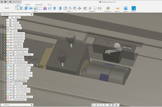
Here's the current rear view:
- Widen / deepen the slot to accommodate the larger ballnut.
- Machine 2 slots for the home and limit switches (on left of this view).
- Machine a slot for the encoder read head (bottom right of view).
- Er...that's it.
- 6200 ball bearing at the rear of the ballscrew, taking the axial loads.
- Flex coupling at the front of the ballscrew. This simply allows manual operation of the ballscrew, as there is no thrust involved, so any minor rotational backlash isn't an issue. I have some 25OD x 30L x 10mm bore couplings on their way from Chinesiumsville even as we speak.
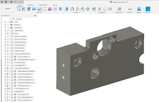
- The grey bracket fixes to the saddle body using existing threaded holes (which seem to be 1/4" BSW), presumably provided for attaching the taper turning attachment.
- The mounting holes are for the aforementioned 1/4" BSW screws and I've provided them with about 1mm of slop so I can adjust the position to ensure minimal misalignment of the ballnut.
- The 2 large through bores are for the rear saddle gib strip which needs to be accessible so I can adjust them in position.
I can just about see my way to machining this from the piece of 4" x 1.5" loominum I have left over from my Bridgeport X and Y axis housings.
What else, fatty?
Yes, that's the delivery from Lichuan ie the servo drives and motors.
That looks pretty painful. Setting up a servo drive can be a royal PITA yet there is no software to assist, so it will all have to be done using the front panel buttons. This could be character forming...
I've also got all the pulleys, belts (both axes), bearings (cross slide) and taps (M2, M2.5, M10x1.0 etc required for mounting the microswitches, encoder head, making the X axis ballscrew nut etc).
The more powerful motherboard is on its way (should be here tomorrow perhaps), the PCI-e to PCI adaptor arrived yesterday (needed so I can re-use the 5i25 - very few mobos these days still have a PCI slot), as did the second D25 connector for the 5i25 and its D25-D25 cable (each of the 7i76 and 7i85 require their own cable back to the 5i25), the 7i85 card arrived on Monday and I received a selection of M2 and M2.5 button head and cap head screws from Kayfast Ltd.
I even received my book on Linux Mint 20. My last one was for the 2013 Ubuntu edition which is thankfully obsolete. Mint has moved the game on a fair way since then, thank Fook.
Finally, I need to figure out how to control the servos using Modbus RS485. I've belatedly ordered a USB-to-RS485 adaptor so this is something else I need to get into. I hope to control them from LinuxCNC over RS485 - apart from the step / dir signals presumably.
No excuse for sitting about then!


No comments:
Post a Comment