Machining action!
After a month or more of buggerage with the Linux PC, I'm pleased to have a diversion in the form of a loominum throttle body housing for a colleague (Toolchimp). Originally the drg called for a piece of 20mm but my cupboard was bare. Mother Hubbard. Finally I twigged that I have a piece of 19mm plate that will do the trick. He modified the model and we have a plan.
Import Solidworks to Fusion 360:
The original model was created in Solidworks and I need to get that into Fusion so I can create the CAM toolpaths etc. Luckily, my paid-for version supports import of SW files rather than forcing export to STP or IGS first. I think this basically means the models have their parametric data.
As well as the model, there's a drawing. Not needed for my purposes but it's good to have something to check the import against.
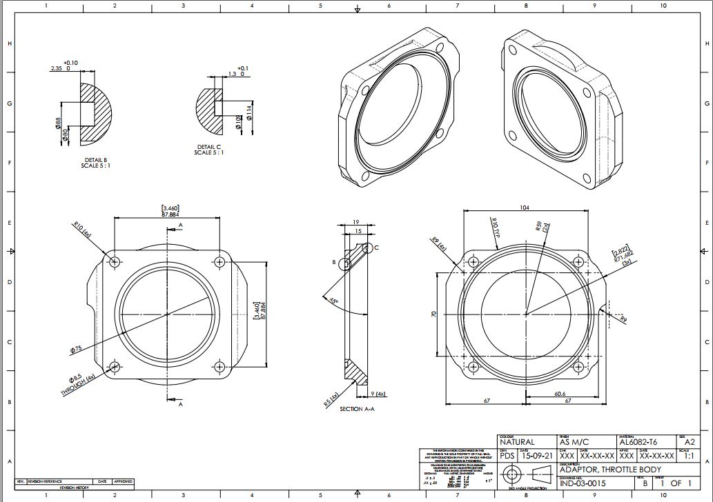
Looks fairly convincing!

Having imported it into Fusion, I created my own drawing so I can figure out stock sizes, tool and toolpath options etc.

Preparing the stock:
This drawing allows me to look for suitable stock. As mentioned, there was a piece staring me in the face. Flash up the bandsaw, which is just big enough to cope with the max dimensions if I flip the piece half way through.


Cool.

Then clean / square it up manually:

Creating the CAM toolpaths:
Then set up the stock and create the toolpaths in Fusion. Top side:
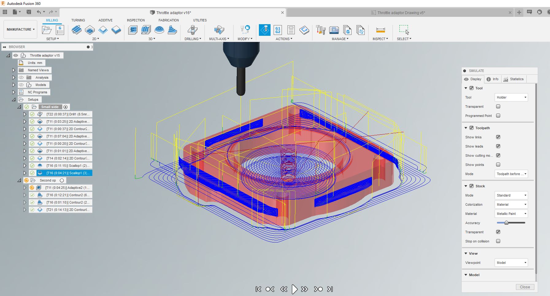
Second operation / bottom side:

This is what we should end up with:

2.5mm groove:
I have a 2.4mm router bit, not a 2.5mm cutter, so will need to cut both directions (2 passes, 0.1mm radially spaced) to end up with the correct 2.5mm width on the smaller o-ring groove. That's easy enough:

Off we go:
So first, drill the 4 holes so I can hold the stock onto a sacrificial base. This is an 8.5mm carbide drill:

Ready for action. Yes, I've ensure the retract height (10mm) is greater than the height of the bolts (8.5mm).

Outline and internal bore and o-ring groove created - now for the fillets:


Sorted. Flip over and pick up the centre line of the bore, which is my origin / datum.

Video of roughing out and (beginning) the finishing of the conical bore. The iPhone and its camera had a bit of a funny turn at this point, so I lost the finishing operation for the conical face:
Had to remove the bolts and use toolmaker's clamps to allow access to the 0-ring groove:

Close but no contact!


Job done:


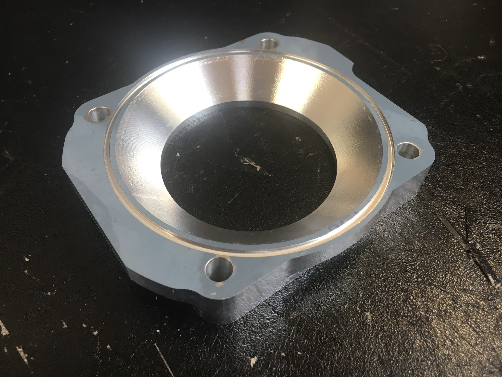
Can't really tell from this pic but the o-ring groove is pretty smooth at the bottom surface:

Contact Point Boundary:
I needed to repeat the final operation to get the base of the conical face like the model. This is to do with the "contact point boundary" option which must be selected, otherwise the cutter won't cut all the way up to the edge of the shoulder. This is what we need / get with the CPB check box enabled in the "geometry" tab of the 2D Contour operation:

Machine / spindle power calculation:
Before running the roughing operation, I thought I'd use my new spindle power calculator to sanity check what sort of margin I have on the available shaft power. I can't imagine this operation would overcome the 3kW Yaskawa drive but it's a good chance to try it out. As expected, it looks pretty reasonable. having said that, I haven't correlated the estimation against any actual figures from the drive during operation.

Closing thoughts:
Came out well. No cockups or broken tools. The paint needs to be stripped off and some minor deburring done - none specified on the drawing and some sections around the bolt holes didn't leave much meat.
Nice one.


No comments:
Post a Comment