What up?
I need to be able to probe both internal and external tools, both left hand and right hand. Most of the probes use the "trilobe" concept, where the probe tip sits on the end of a sort of tripod scheme, with the 3 legs held against electrical contacts by a spring. It's what I have on the Renishaw MP1S and TSR27 probes used on The Shiz to good effect. This principle works fine for mill probing which only occur in 5 axis (+/- Z, +/-Y and -Z directions) but if you try to "pull" the tip away from the probe body in the Z direction, bad things would happen.
In an idle moment (couple of hours), I modelled the DIYO probe in Fusion 360 and uploaded it onto Grabcad. Looks good but the purpose was to be able to use it to design an assembly, taking into account the rather limited movement available on the key components that make up the cross slide, turret, tailstock etc.


In simple terms, the external toolholder and the internal (boring bar etc) toolholders don't present their tips at quite the same radial position. True, most of the external toolholders have a well defined length (125mm from the back the tool holder to the tip) and height (0.75" from the base of the toolholder to the cutting tip) but the radial position of the boring bar tip will depend on the diameter of the boring bar and the length of the tip.
NB: On this machine, the probing move needs to be in different directions for the internal and external tools. The cross slide can only move away from the centre line (away from the operator), which means that the boring bars will be presented "upside down" with the spindle rotating clockwise. In contrast, the external tooling has to be "left handed", presented "right way up", with the spindle rotating counter clockwise.
This probe assembly is going to be hazardously close to the hydraulically powered turret, so a turret indexing move could easily destroy it. So my cunning plan is to mount the probe on a swing arm, with the tip pointing down. That way, if the turret indexes when the probe is in position, it stands a chance of pushing the probe out of the way rather than trashing it.
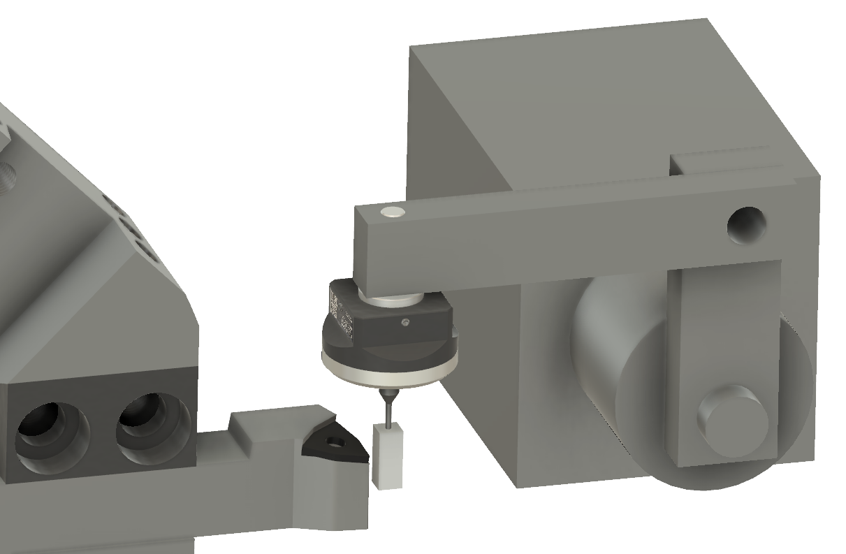
This looks workable, although I may be advised to test out the probing moves before getting too far into the build. The "build" itself is actually fairly simple, comprising little more than the swing arm assembly, now that I have done the calculations and figured out a scheme that appears to actually work.


No comments:
Post a Comment