Bollocks. Stupidly, I let The Stupid Fat Bloke set up the part in The Shiz and program the drilling / boring operations using dimensions from the 2D Drawing.


But all is not yet lost, thankfully. The answer is to create another 3 holes for the cam studs, resulting in a total of 6. Three of them will stand as testament to the power of idiocy. These won't be so obvious when the chuck is fitted but the only alternative would be to start again and make another body from stock. Seems the path of least waste that my laziness will appreciate.
So firstly I will carry out the radial drilling / boring operation in the 4th axis, before replacing the thing in the vise and drilling / boring the additional 3 axial holes.
Initial step will be to (carefully) set up the work for the 3 radial bores. Luckily I'd set up the 4th axis during the last session, so apart from double checking, there's not a lot of actual, setup to do.

Off we go. However, I soon determined that my scepticism about the Indian 3-jaw chuck having enough grip to withstand the drilling forces required to force a 12mm drill through were justified. Never mind - this block of loominum can hold it in place against the jaws.

Nice finish from the boring bar.


Now back to the horizontal setup. How to align the holes? Actually, the Centroid software allows you to use CSR ("coordinate system rotation") to reorientate the machine axes to a measured direction that is picked up by to probed points. In this case, I've got couple of tight fitting 12mm end mills and a straight edge. The Y axis will then be aligned to these 2 holes that are intended to be on the same Y coordinate.
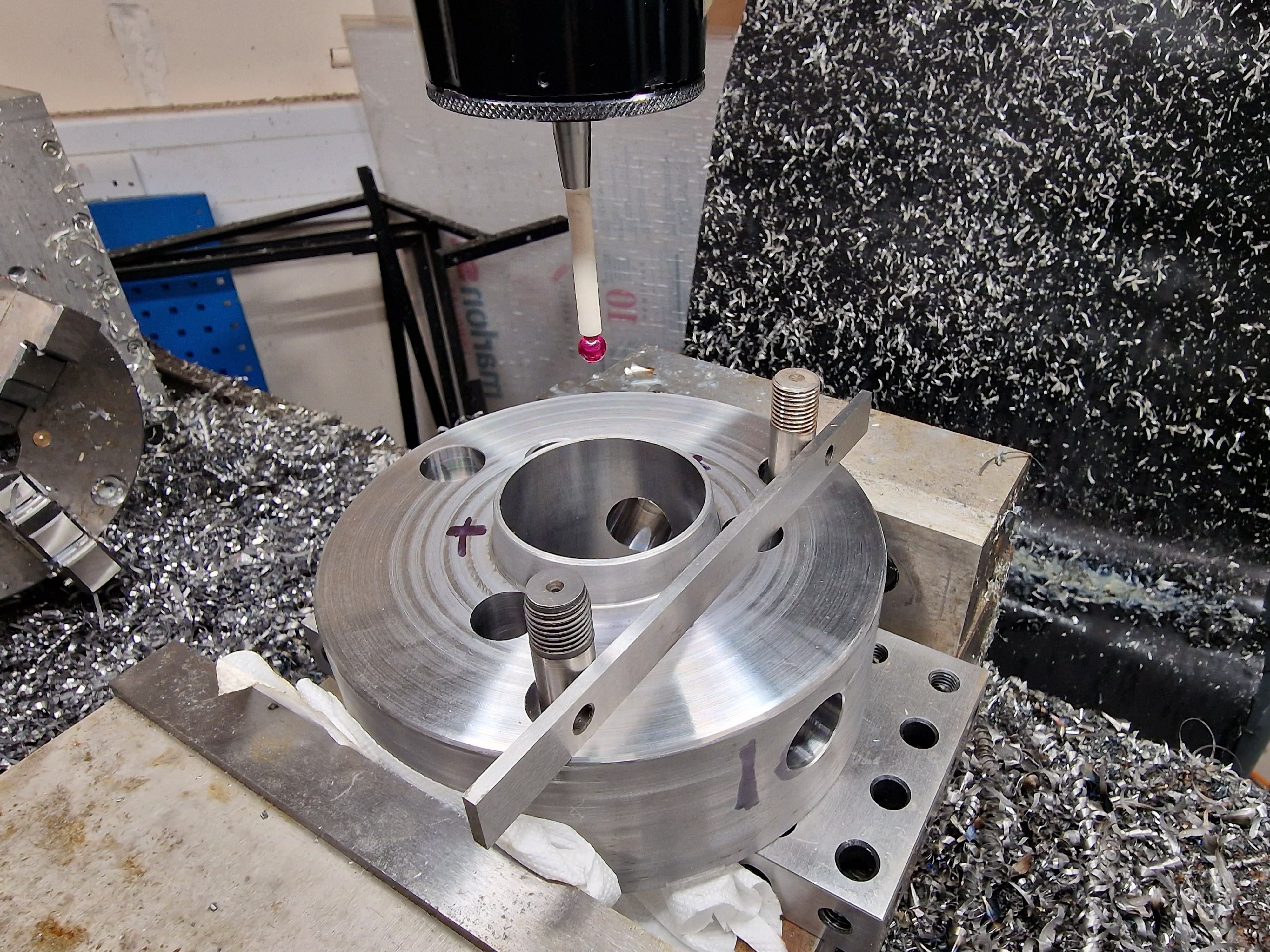
With that done and some sanity check probing on the existing hole positions, I can get drilling and boring again.


That's the 12mm holes drilled.

...and bored


But - does it fit? Yes:

The cam studs are visible in the radial bores. They look about right.

Looks pretty good, if you ignore the 3 idiot holes:


Cool - I should be happy with that. Next I need to focus on the cam studs...


No comments:
Post a Comment