Any resolution on the hardware yet?
After endless rabbitholing, I've gone for the smallest, simplest microcontroller in the end. No need for pointless displays or masses of IO here.
Currently, I'm using the "DUBEUYEW ESP32-C3 Development Board Mini " obtained through Amazon.
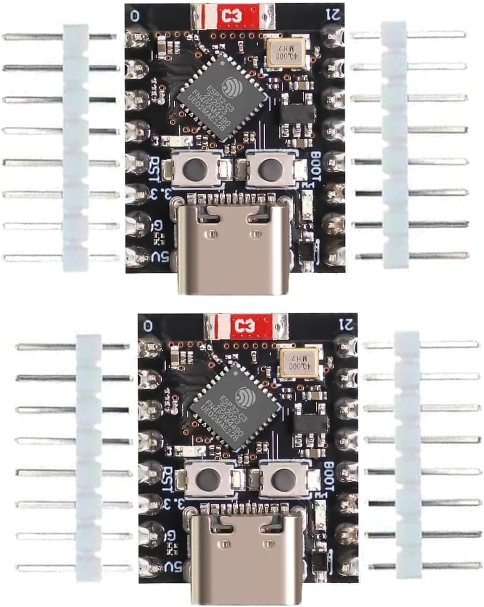
Being a C3 version of the ESP32, it has a single core micro. Here is some useful background on it, including the pinout etc.
So obviously I've ordered an "S3" equivalent "Waveshare ESP32-S3 Mini Development Board, based on ESP32-S3FH4R2" which has 2 cores.

This dual core S3 version should allow me to run the "MIG pulsing" software independently to the "torch motion" code, as I found the stepper code was rather lumpy and didn't get on well alongside the pulsing code. To be fair, the Arduino Uno R4 isn't the same as the ESP32, so I can't compare their speeds directly and can't be bothered to do any testing myself.
Got anywhere with the motor and driver?
Well, I've decided to ditch the stepper driver software for now, unless it turns out it's the only way to go. Instead, I'm hoping to pass the bulk of the task off to a pukka servo device like this, also from Waveshare.

Although you can't see it easily from this angle, it's double ended and comes with metal flanges for each end. So I should be able to make up wheels with o-ring tyres, rather like the little bogey I previously constructed.
The datasheet for this ST3215 looks encouraging, although it uses an RS485 serial bus for control, so I'll need to look into that more closely.
There are some examples to help applying this servo, although the default expectation is that you will use one of their ESP32-based "driver boards". They refer obliquely to "secondary development" where you can drive the servo yourself without the driver board. This is the route I'd want to go, as I don't want / need an additional ESP32 just to drive the servo.
But - how's the software coming along, Fatty?
Well at least that seems to have largely resolved itself for now. I've got the pulse frequency / duty cycle functions working nicely now:
- Pulse width setting is managed within function managePwm();
- Pulse frequency (period) is managed within function managePeriod();
- These use "non-blocking" operations (rather than "delay" which causes the micro to go on hold for the duration)
- Currently, motorSpeedIn is simply set by reading a pot and generating a value from 0 to 4095. I will use this to control the servo, once I've figured out what I need to do.
- For debug purposes, I have a reportStatus() function to drive the serial monitor, showing the current values of pwmDuration, pwmPeriod and motorSpeedIn.
Here's the code in its entirety:
#include <Arduino.h>// Muzzer 18th March 2025// Select "LOLIN C3 Pico" to compile for the tiny ESP32const int pwmPin = 8; // the number of the (blue) LED pin on the ESP32 C3 Picoconst int dutyCycleAnalogIn = A0; // Analog input- PWM dutyconst int periodAnalogIn = A1; // Analog input - period (ms)const int speedAnalogIn = A2; // Analog input - speed (Hz)const int maxPeriod = 3000; // hard coded max pulse time in msconst int minPeriod = 500; // hard coded min pulse time in msconst int minDuty = 20; // hard coded min duty %int pwmState = HIGH; // Led state for PWM outputint pwmSensorValue = 0; // Value read from the pot - for debug onlyint periodSensorValue = 0; // Input from pot - for debug onlyint motorSpeedIn = 0; //long previousMillisPwm = 0; // Last time PWM output was updatedlong previousMillisPeriod = 0; //long pwmDuration = 2000; // Interval for PWM output (milliseconds)long pwmPeriod = 2000; // Interval between spots (milliseconds)unsigned long currentMillis = 0; // Initialise current timevoid setup(){Serial.begin(9600); // Start the Serial MonitorpinMode(pwmPin, OUTPUT); // Set the selected PWM output pin as an OUTPUT}void loop(){currentMillis = millis(); // capture the current timemanagePwm(); // Terminate mark when the time is rightmanagePeriod(); // Start new mark at the end of the periodreportStatus(); // Debug output to Serial MonitormotorSpeedIn = analogRead(speedAnalogIn); // Define setSpeed() according to input A2 (0...4095)}void reportStatus(){Serial.print("Duty time is");Serial.print("\t");Serial.print(pwmDuration);Serial.print("\t");Serial.print("Period time is");Serial.print("\t");Serial.print(pwmPeriod);Serial.print("\t");Serial.print("Output");Serial.print("\t");Serial.print(pwmState);Serial.print("\t");Serial.print("Speed Input");Serial.print("\t");Serial.println(motorSpeedIn);}void managePwm(){pwmDuration = map(analogRead(dutyCycleAnalogIn), 0, 4095, (pwmPeriod*minDuty/100), pwmPeriod); // map input to pwmDuration - on time//check if it's time to terminate the PWM output yetif(currentMillis - previousMillisPwm > pwmDuration){//store the time of this change// LOW = OFF: end the pulse. NB: LOW actually lights up the LED!pwmState = LOW;digitalWrite(pwmPin, pwmState);}}void managePeriod(){pwmPeriod = map(analogRead(periodAnalogIn), 0, 4095, minPeriod, maxPeriod); // pwmPeriod = time between spots//check if it's time to reset the output to start the next pulse yetif(currentMillis - previousMillisPeriod > pwmPeriod){previousMillisPeriod = currentMillis;previousMillisPwm = currentMillis;// HIGH = ON: reset the output for next pulsepwmState = HIGH;digitalWrite(pwmPin, pwmState);}}
- Figure out how to drive this ST3215 servo thing from the ESP32 C3 / S3
- Do I need to go to dual core operation to get the pulse and motion functions to play nicely?
- Does the S3 work the same as the C3 or will I need to mess with the code? Should be relatively quick and easy to find out...


No comments:
Post a Comment