The simulation sort of shows the general idea but wouldn't necessarily work as shown in my application:
- The 431 doesn't like more than about 36V on its cathode. I will need a series zener diode to reduce the max voltage it sees.
- I need to ensure at least 1mA in the 431 to keep it "lit", yet I need also to ensure that 1mA in the potchain doesn't turn the IGBT on.
- I may need some capacitance across the 431 to keep it stable. Possibly not - but it needs to be considered.
- I have only a limited selection of components - despite the sacks on obsolete stuff I've accumulated over the years, I don't have "comprehensive coverage" of all compt types and values.
Let's see what compts I can find after a good rummage in my "stuff":
- BZX85-C27 ie 1.3W zener, 27V +/- 5%
- BZX85-C15 ie 1.3W zener, 15V +/- 5%
- 470uF 35V electrolytic
- 100uF 35V electrolytic
- 4.7uF 400V electrolytic
- 22uF 160V electrolytic
- 100k single turn pot (Chinesium - acquired for the Motorhead controller)
That looks like a good start. Along with the RS431 voltage regulators (a Chinesium clone of the original TL431) and the Big Fuck Off IGBT modules, I should have everything I need. So now, let's do some sensible calculations to make this thing work in my application:

Here's the RS431 datasheet - it's a Chinesium clone of the industry standard TL431, originally from TI:

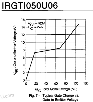

You can see from the old datasheet that the gate threshold is pretty soggy but typically lies around 5-8V. BUT - bollocks to this. If I simply put two 27V zeners in series with the gate threshold, I might expect around 60-64V operation of the device. Hell, this would be a lot simpler than buggering about with 431s.
I can't be arsed to put it into SIMetrix Here's the circuit:

The zeners would need to pass at least 2mA or so before thew B.F.O. IGBT would conduct, so they would be well into their "flat" region. Equally, a 2mA current wouldn't overheat them by a long chalk.
The 15V gate zener would protect the IGBT against overvoltage and its 1k resistor would limit the current if the input exceeded ~69V (ie 27+27+15).


No comments:
Post a Comment