Wednesday, 7 April 2021

Fusion work - solid toolpost and cross slide rear cover

Got up yesterday, forgetting that I'd booked the week off. Once the Domestic Manager and my line manager had reminded me of the fact, I realised I had some workshop time to hand. I have some components to make for the Bantam still - but that requires me to model them up in Fusion first:

  • Cross slide ballscrew extension. To allow me to refit the original micrometer handle and keep the original look of the machine. For now I have a plastic handwheel that came off the Bridgeport downfeed. Looks crap but does the business for now. It has a splined section to connect to the micrometer handle and a 10mm end for the spider coupling to the ballscrew. Not a complex part but I will have to turn it on the Bantam before splining it on The Shiz. Sounds like something to do when the machine is finally working as a CNC lathe.
  • Rear cover for the cross slide ballscrew. Currently, the ballscrew and microswitch are exposed when the cross slide is at the extreme of movement (away from the centre line). This is little more than a U-shaped rectangular lump that bolts on the back of the cross slide.
  • Solid pillar for the toolpost. There's no point having a top slide / compound slide on a CNC machine and it simply adds compliance, slop and backlash, so best omitted altogether. 
Multifix toolholder:
Couldn't find any CAD models for the "A" size Multifix toolholder on the internet, so I got out the calipers and modelled it up myself. Came out well. It wasn't really needed, other than for visual effects but felt like a relaxing diversion. Uploaded to Grabcad.

With 90mm toolholder:

Solid toolpost:
Then I modelled up the toolpost pillar thing. It's a lofted body, spanning the base of the Multifix toolpost and the cross slide. Furthermore, I have a piece of mystery loominum (probably 6061) that's almost the right size - 4.4" x 4.5" x 85mm, so these dimensions work for me. Perhaps steel would be better but I don't have anything to hand so for now it will have to suffice.


For machining out the outside surface of this part, I'll use the Korloy 50mm shell cutter, as the convex surfaces are all easily accessible. Then I'll use the trusty 10mm end mill for the counterbores etc. Finally, invert it and face off the 5mm or so I will have used to hold it in the vise.

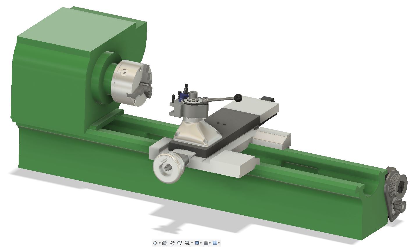
Here's a view of the assembly on the machine:


Bantam CAD model with head:
And yes, while I was at it, I created a headstock assembly for the Bantam. Fairly basic but more representative than the bare bed assembly I have been using so far:

I might be tempted to create a tailstock at some point, to bring it to something closer to completion.

Rear cross slide cover:
The rear cover is simple enough:


Again, the 50mm shell cutter should work nicely here. It's easy to forget that these cutters are not simply for skimming faces. They have 90 degree edges and the axial length is something like 11mm.

Ballscrew extension:


Time to flash up the 4th axis again. This will require a 2mm end mill. I have loads of them from a mixed batch of carbide PCB router bits, some in pretty good shape.


As I said, the ballscrew extension can wait for now.

Z axis limit switches - fitting and setup

I can't home the Z axis and set sensible soft limits until I've got a home/limit switch fitted to the tailstock end and a limit switch to the headstock end.

I bought some Honeywell limit switches last week, which finally arrived yesterday. They turn out to be a waste of money if I was planning to use them for homing. There's so much slop they are only usable for overtravel protection. Bollocks.

So instead, I will use these proximity switches. I still have a load of them left over from the Bridgeport conversion. I was a bit concerned about the possibility of false triggering due to swarf but for now this isn't a major concern and I may be able to shield them anyway.


Fitting:

Some cable extension required to get the sensors wired into the 7i76 card.

Little bracket (just a strip of loominum) mounts into M6 holes on the back of the encoder head. The sensors then screw onto those with M3 CSK screws. The target is a piece of angle section, simply held to the encoder body with double sided tape. Sounds Heath Robinson but I'm worried it may actually be challenging to remove later - some heat may be required.

There's no adjustment in this setup but I can recreate this later with some slotted holes perhaps, either for the sensors themselves or the target.

Setup:

This entry in the HAL file connects up the switches:

# external input signals

# --- MAX-HOME-X ---
net max-home-x <= hm2_5i25.0.7i76.0.0.input-00

# --- MIN-X ---
net min-x <= hm2_5i25.0.7i76.0.0.input-01-not

# --- MAX-HOME-Z ---
net max-home-z <= hm2_5i25.0.7i76.0.0.input-03

# --- MIN-Z ---
net min-z <= hm2_5i25.0.7i76.0.0.input-02


Followed by this for the Z axis:

# ---setup home / limit switch signals---

net max-home-z => joint.1.home-sw-in
net min-z => joint.1.neg-lim-sw-in
net max-home-z => joint.1.pos-lim-sw-in

Homes beautifully. The current extent of movement is around 420mm, so the soft limit is set at 410mm. I can rapid into the soft limits at either end without overshooting and overshooting enough to trip the limit switches. Nice.

Monday, 5 April 2021

X and Z axis PID setup finalised!

Finally figured out the PID settings for the Lichuan servos and the LinuxCNC PID controllers. It's rather important to get the STEPGEN_MAXVEL and STEPGEN_MAXACCEL values high enough, otherwise the stepgen won't allow the servos to move fast enough to satisfy the PID controllers. 

This is what I ended up with on the X axis.  

STEPGEN_MAXVEL = 125
STEPGEN_MAXACCEL = 750
P = 60
I = 40
D = 1
FF0 = 0
FF1 = 0.4
FF2 = 0.01
BIAS = 0
DEADBAND = 0.0045

The FF1 is similar to the D term but the effect is slightly different, so I found there was benefit in playing with both. Similarly, the FF2 (a second derivative of the position error) was beneficial although the value is very critical. Intuitively, the term addresses the inertia of the system.

Let's just say, the performance looks pretty reasonable.

Can't complain about that. It's certainly a lot better than what I was seeing a couple of days ago and it's a Good Thing I didn't give up back then.

Saturday, 3 April 2021

LiChuan configuration "software" - setup and use??

Setting up the servo tuning(?) software:
Having spent a couple of hours yesterday pratting about with the PID controllers for the X and Z axes, I seem to have arrived at something approximating to the best I can expect from my setup. It may not be stunningly good but it's a lot better than I'd ever achieve when using the machine in manual mode.

Ideally I'd have tuned the servo drives on their own before tuning the outer position loop within LinuxCNC. However, the "software" provided by Lichuan is almost unusable. For a start it won't even run on most of my Windows 10 machines. Finally, having installed it on 4 of them, I have a laptop that will both actually run it - and have it speaking English to me. Whoopeee shit. Another 2 hours of my life I will never get back, as they say.

Here's the link to download page where you download said "software", along with the "user manual". The "detailed" version of the manual is only available in Chinese but contains little more than the "simplified" version.

I then needed to download the driver for the USB-RS485 device before I could connect to the servo drive through a serial port (COM3) using a hacked ethernet cable:

Show time!
This revealed the "software" in all its glory. It's just a table of parameters that you download from the drive. You can change the values in the light blue column and then upload it back to the drive. That's it.


There are also a couple of pages for configuring the digital IO:


And showing the status of the ports etc.


Bottom line?
Pretty simple really. When it comes to PID settings, the only value I can change in the positional control mode is the direct gain (P), which is initially set to 20. There are no I or D term parameters. I suppose that keeps matters simple but means I'm stuck with what I've got. Bollocks.

PID tuning the X and Z axes

Setting up the tools:

I set up the "configuration" tool using the menu within LinuxCNC. This allows you to change the main PID parameters and test them on a live system. 

Also set up the Halscope tool (also available from the manu) to display the demand and follow error signals, so get an idea of how the changes were affecting the response. And turning round to observe the ballscrews rotating - nothing like a visual to get a feel for how good it actually is in the metal. 

First settings for the X axis that seemed almost workable:


Almost final values:


You can write the values back to your INI file (if you choose). Here's what I've got so far:

[JOINT_0]
TYPE = LINEAR
# HOME is the distance the axis moves - AFTER setting home position zero
# MAKE CERTAIN IT IS NEGATIVE ON X AXIS!!
# It can be within the soft limits but will error if it's not.
HOME = 0.000
FERROR = 10
MIN_FERROR = 1.00
MAX_VELOCITY = 50
MAX_ACCELERATION = 100.0
BACKLASH = 0.000
....

STEPGEN_MAXVEL = 125
STEPGEN_MAXACCEL = 750
P = 30
I = 0.2
D = 5
FF0 = 0
FF1 = 1
FF2 = 0
BIAS = 0
DEADBAND = 0.0025
MAX_OUTPUT = 0
....


[JOINT_1]
TYPE = LINEAR
HOME = 0.0
FERROR = 300.0
MIN_FERROR = 1.0
MAX_VELOCITY = 100
MAX_ACCELERATION = 200
# What are these scale things?
BACKLASH = 0.000
....
STEPGEN_MAXVEL = 125
STEPGEN_MAXACCEL = 200
P = 80
I = 5
D = 20
FF0 = 0
FF1 = 1
FF2 = 0
BIAS = 0
DEADBAND = 0.005
MAX_OUTPUT = 0

..for the record.

And this is what I see on the Z axis. Hardly a text book example of servo response:

I started off with the X axis which is a simpler assembly, turning up P from 1 until it started to oscillate around 50, then backed it off to 30 and dialled in some D, trying to speed up the response without significant overshoot. I couldn't improve much on D=5. Finally, some I term. I couldn't see much improvement beyond I=0.2.

With the Z axis, I ended up with P=80, I=0.5 and D=20.

Where did that get you, fatty?

The response is hardly a textbook example of a well tuned servo system. I get a fairly rapid initial move, followed typically by a slower creep up to the final position. Given that P and D are about as high as they can go sensibly, I'm not seeing any great opportunity to improve on that. Ideally I'd be getting there mostly due to the P and D terms, with the I providing a last, steady state adjustment.

There's a lot going on in reality, so this isn't quite a simple mass spring damper type situation. There are 3 factors making life less than straightforward:

  1. The mechanisms both have a degree of backlash and although I've taken care to minimise them, they are of the same order as the movements I am trying to optimise ie ~+/-10-20um. I have reasonably good quality Korean ground ballscrews but the lathe itself (Colchester Bantam) has seen better days and the saddle is being driven some way from its centre of mass and the likely line of action of the cutting forces. The Z axis is less ideal than the X, not surprisingly, due to the vee and flat ways and larger mass.
  2. The encoders have "5um" resolution, so realistically I can't expect to control position much better than somewhere in the region of +/- 5-10um surely.
  3. The Lichuan servo drives will be a pig to try to tune. The absolute first thing to do in a dual control loop system like this would surely be to get the servos as optimised as possible before playing with the external (LinuxCNC) loop. However, the tuning "software" is no more than a means of downloading and uploading the table of parameters from a PC to the drives and I don't seem to be alone in being unable to even load the "software" on a W10 machine. So I've started out with the standard tune, which I suspect is pretty ropey and must be limiting what I can do.
So I have 2 hysteretic elements (backlash and encoder resolution) and servo drives with questionable responses. I can feel a battle with the Lichuan servos coming on, otherwise I suspect I am close to what I can expect as a final result.

Grumble and jitter:
Given the 5um resolution of the encoders, what is the recommended deadband? I'm guessing somewhere between 2.5 and 5um but I can't figure out a convincing logical answer to that. Certainly, increasing the deadband towards the 5um (0.005) level seems to get rid of much of the grumbling / jittering that arises after some moves.

I seem to have inherited FF1=1, presumably from the original CNCconf setup. The other FF terms are zero. I did play with a couple of them and it didn't end well, with the joint drifting out of position, so I left them as they were. I don't have any high frequency bursts going on but until I reread the docs, I'm not clear if I'm missing anything here.

Still to be resolved:
Finally, how do the STEPGEN_MAXACCEL and STEPGEN_MAXVEL affect the PID behaviour? Presumably they will affect the slope of the rising edge of the demand step I'm using to observe the system response, which would in turn affect the effect of the D feedforward term for instance.

Getting an ESP32-S3-Mini to talk to an HX711 load cell amplifier and the Bojke laser distance sensor

It's all very well using that large DIN Rail-mounted ESP32-S3-POE-ETH-8DI-8DO to talk to the laser sensor and load cell but it feels a b...